
P0031 on 2005-2008 Audi A4 2.0T: HO2S Heater Circuit Low Causes and Fixes
On a 2005-2008 Audi A4 2.0T, code P0031 almost always means the internal heater in the upstream oxygen sensor (Bank 1, Sensor 1) has failed. The most common fix is to replace the sensor. Expect to pay ~$70-$150 for a quality aftermarket part (like Bosch) or ~$180-$250 for an OEM sensor. DIY difficulty is 2/5.
- P0031 on your A4 2.0T almost always points to a problem with the upstream (pre-catalytic converter) oxygen sensor.
- The most likely fix is to replace the sensor itself. Using a quality brand like Bosch (the OEM supplier) is highly recommended for longevity.
- Before buying parts, perform a quick visual inspection of the sensor's wiring for any signs of melting or damage due to the nearby turbocharger.
- As a simple second step, check the fuses for engine electronics in both the dashboard and engine bay fuse boxes, especially if you have other 'circuit low' codes.
What's Unique About the 2005-2008 Audi A4
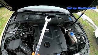
On the B7 generation Audi A4 with the 2.0T FSI engine, the upstream O2 sensor and its wiring are positioned close to the hot turbocharger and exhaust manifold. This high-heat environment makes both the sensor's internal heater and the external wiring harness prone to failure over time. It's not unusual for the wiring's protective sheathing to degrade, leading to melted wires or shorts that can also trigger a P0031 code. Many owners on forums like Audizine and AudiWorld have documented this specific issue.
Symptoms You May Notice
- Check Engine Light is on
- Decreased fuel economy
- Rough idle, especially on a cold start
- Failing a vehicle emissions test
- Slightly rougher engine performance until warm
- Replacing the downstream (post-catalytic converter) oxygen sensor. P0031 specifically refers to Sensor 1, which is the upstream sensor.
- Replacing the sensor without first checking the wiring and fuses. 🎬 See why new sensors fail if you skip these checks A melted wire or blown fuse will cause the new sensor to not work and the code to return immediately.
Most Likely Causes
- Failed Upstream Oxygen Sensor (Bank 1, Sensor 1) 🔴 High Probability → Shop Oxygen Sensor The internal heating element is a common wear item and its lifespan is shortened by the high heat environment near the turbocharger. Bosch is the original equipment manufacturer for this sensor on many Audis.
How to confirm: Disconnect the sensor and measure the resistance between the two heater wires 🎬 Watch: How to test the heater circuit with a multimeter (on a Bosch sensor, these are typically the two white wires). A reading of infinite resistance (open circuit) confirms the heater has failed. A healthy heater typically has a low resistance, often between 2-20 ohms when cold.
Typical fix: Replace the Bank 1, Sensor 1 oxygen sensor. It is located on the turbocharger outlet/downpipe and is accessible from the top of the engine bay, sometimes requiring removal of the air filter box for better access. Apply anti-seize to the threads of the new sensor before installation.
Est. part cost: $70-$250 - Damaged Wiring or Connector 🟡 Medium Probability The wiring harness is routed very close to hot exhaust and turbo components, which can cause the insulation to become brittle, melt, or chafe over time, leading to a short or open circuit. This is a well-documented issue on B7 A4 forums.
How to confirm: Visually inspect the entire length of the sensor's wiring harness from the sensor to the firewall connector. Look for any signs of melting, chafing, or broken wires. Pay close attention to where the harness may contact the engine or heat shields. Check the connector for corrosion or pushed-out pins.
Typical fix: Repair the damaged section of wire using heat-shrink butt connectors and high-temperature wire loom. Secure the repaired harness away from hot surfaces using zip ties. If the connector is damaged, replace the connector pigtail.
Est. part cost: $10-$50 - Blown Fuse ⚪ Low Probability If the sensor's heater element or wiring shorts to ground, it can blow the fuse that supplies power to the circuit. This is more likely if multiple O2 sensor heater codes (e.g., P0031, P0037, P0051) appear simultaneously.
How to confirm: Check fuses in the engine bay fuse box (under the plenum cover near the ECU) and the interior fuse panel (driver's side dash). Specifically for the 2.0T FSI, check fuse #34 (15A) in the engine bay E-box and fuse #29 (10A) in the driver's side dash panel, which are commonly associated with engine electronics and O2 sensor heaters.
Typical fix: Replace the blown fuse. If the new fuse blows immediately, it confirms a persistent short circuit exists in the wiring or the sensor itself which must be found and repaired.
Est. part cost: $1-$5
Rare But Worth Checking
- Faulty Engine Control Module (ECM): This is very uncommon and should only be considered after all other possibilities (sensor, wiring, fuses) have been thoroughly tested and ruled out. A failed driver circuit within the ECM can mimic a sensor or wiring fault.
Diagnosis Steps
- Scan for Codes: Use an OBD-II scanner to confirm P0031 is present and check for any other codes. If codes for other heater circuits (like P0036, P0051, P0057) are also present, suspect a shared power or ground issue first, like a fuse.
- Inspect Wiring: Visually inspect the oxygen sensor's wiring harness from the sensor itself to its connection point at the firewall. Look for any signs of melting, chafing against the engine, or other damage. This is a critical step on this platform due to heat from the turbo.
- Check Fuses: Check the fuses related to engine electronics. Start with the fuse panel on the driver's side of the dashboard, specifically position #29 (10A). Also inspect the fuse box in the engine compartment plenum (E-box), checking position #34 (15A).
- Test the Heater Circuit Resistance: Disconnect the O2 sensor. Using a multimeter set to Ohms, measure the resistance across the two heater pins on the sensor side of the connector (they are often the two white wires on a Bosch sensor). A reading of infinity or 'OL' indicates a broken heater element, and the sensor must be replaced. A normal reading is typically low, between 2 and 20 Ohms.
- Test for Power at the Connector: With the sensor unplugged and the ignition key in the 'On' position, use a multimeter to check for battery voltage (approx. 12V) at one of the pins on the vehicle-side harness connector. If no voltage is present, it confirms a wiring or fuse issue upstream.
- If all other steps pass, the oxygen sensor is the most likely failed component and should be replaced.
Parts You'll Likely Need
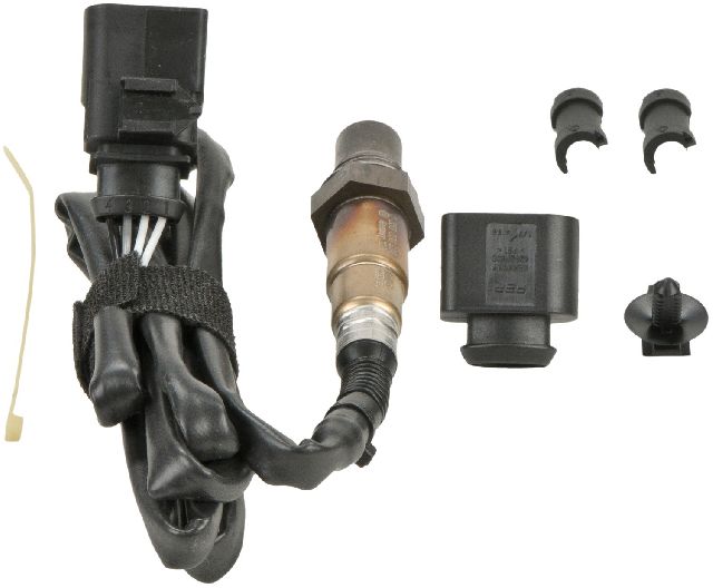
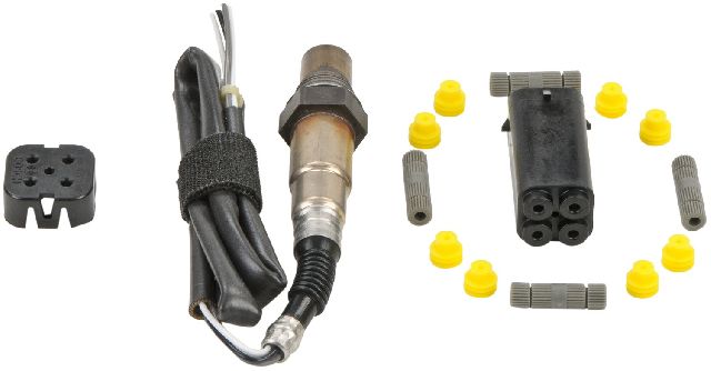
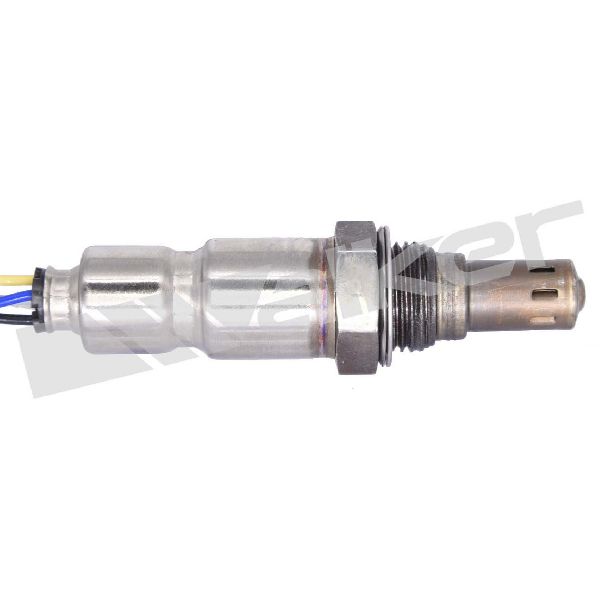
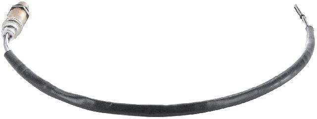
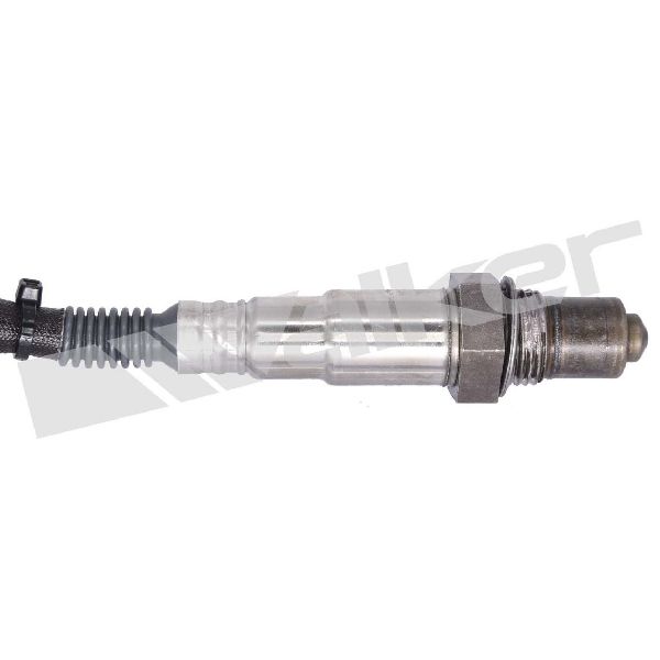
- Upstream Oxygen Sensor (Bank 1, Sensor 1)
(OEM #06F906262F)— The internal heater element is the most common failure point for code P0031 on this vehicle.
Trusted brands: Bosch (OEM supplier), Denso, NGK/NTK
OEM price range: $180-$250
Aftermarket price range: $70-$150
Related Codes That Often Appear With This One
- P0036 — This is the heater circuit code for the downstream sensor (Bank 1, Sensor 2). If both P0031 and P0036 appear together, it strongly suggests a common power supply issue, like a blown fuse or a faulty relay that powers both sensor heaters.
- P0135 — This is a more generic code for 'O2 Sensor Heater Circuit Malfunction (Bank 1 Sensor 1)'. It often appears with or is closely related to P0031, pointing to the same set of potential failures.
- P0171 — System Too Lean (Bank 1). While not directly related to the heater circuit, a failing O2 sensor can eventually lead to incorrect fuel trim adjustments, potentially causing lean or rich codes. A vacuum leak is also a common cause for P0171 on this engine.
Platform-Specific Known Issues
- Melted Wiring Harness: A user on Audizine reported their P0031 code was caused by the O2 sensor wiring harness melting against the turbocharger heat shield. The fix involved repairing the wires with a pigtail and securing the new harness away from the heat source. This highlights the importance of the visual inspection step.
- DIY Replacement Story: An owner on the AudiWorld forums detailed their DIY replacement of the Bank 1 Sensor 1. They noted that removing the airbox provided significantly more room to work and access the sensor. They used a 22mm O2 sensor socket and a long extension to remove the old sensor. The total job took about 45 minutes.
Mechanic-Grade Diagnostic Values
- O2 Sensor Heater Resistance (Cold) — expected: 2-20 Ohms. Failure: Infinite resistance (Open Line) or 0 Ohms (short). A reading outside the 2-20 Ohm range suggests a failing heater element.
- O2 Sensor Heater Resistance (VCDS Live Data) — expected: Rises with temperature, may show ~40-50 Ohms when hot.. Failure: An extremely high value (e.g., >200 Ohms) or a value that doesn't change from cold suggests a fault in the sensor or wiring.
- Voltage at O2 Sensor Harness Connector (Heater Power Pin) — expected: ~12V (Battery Voltage) with Key On, Engine Off.. Failure: 0V or significantly low voltage indicates a problem with the power supply, likely a blown fuse or a break in the wire from the fuse box.
Scan Tool Commands That Help
- VCDS (VAG-COM): Engine -> Measuring Blocks -> Group 032 (Fuel Trims) — To check long-term fuel trims before and after the repair. A faulty sensor often causes high fuel trim values (e.g., > +/- 10%). After replacement, these values should return closer to 0%.
- VCDS (VAG-COM): Engine -> Basic Settings -> Group 034 (Lambda Control) — To run a test of the oxygen sensor system. The screen will show the B1S1 voltage cycling and the test status (e.g., 'Test ON', 'B1-S1 OK'). This can help confirm if the new sensor is operating correctly after installation.
- VCDS (VAG-COM): Engine -> Advanced Measuring Values -> Search for 'Lambda probe heater resistance' — To view the resistance of the heater circuit as calculated by the ECU. This can be a quick way to confirm an open circuit (very high resistance reading) without physically accessing the sensor connector.
Wiring & Ground Locations
- Ground Point 12 — In the engine compartment, on the left side, near the firewall/plenum.. This is a primary ground point for engine electronics, including the ECM. A corroded or loose connection here can cause a variety of intermittent electrical issues, including sensor circuit faults.
- Ground Strap - Engine to Body — Typically runs from the engine block (near the turbo/starter area) to the chassis frame rail.. Ensures the engine block has a solid ground reference to the chassis and battery negative. A weak or broken strap can cause the ECM to see incorrect sensor readings and set circuit codes.
- T6c Connector — This is the 6-pin black connector for the upstream oxygen sensor, located near the firewall on the driver's side of the engine bay.. This is the primary connection point to test for power, ground, and resistance. Pins 1 and 2 are typically for the heater circuit. Pin 1 receives 12V power from a fuse, and Pin 2 is the ground provided by the ECM.
Real Owner Repair Stories
- Audizine Forum Member (2007 Audi A4 2.0T) — P0031, P0036, P0136, P0141 - multiple O2 sensor heater and circuit codes appeared at once.
❌ Tried (didn't work) Initially suspected multiple sensor failures.
✅ What actually fixed it Found a blown 15A fuse in the engine bay fuse box (E-box). Replacing the fuse cleared all codes. The simultaneous failure of multiple heater circuits was the key clue pointing to a common power supply issue.
OEM Part Supersession History
06F906262F→1K0998262D, 06J906262AA— Part consolidation and minor revisions by the manufacturer.
Heads up: While multiple part numbers may fit, it's crucial to use a sensor specified for the 2.0T FSI engine. Using a sensor from a 1.8T or a later TFSI engine may cause incorrect readings even if it physically connects. The Bosch 17351 is a confirmed compatible aftermarket part.
Model Year Variations Within This Range
- 2005-2008: Within the B7 A4 2.0T, there were different engine codes (e.g., BPG, BWT). While the P0031 diagnosis is identical, it's important to provide the correct engine code when ordering parts, as minor differences in other components exist. However, the upstream O2 sensor and its function remain the same for this fault.
Diagnostic Flowchart
Other Known Issues on This Vehicle
Issues unrelated to this code that are worth knowing about as an owner of this generation:
- HPFP Cam Follower Failure 🔴 High — Extremely common. Recommended inspection/replacement every 20k-30k miles. Failure can destroy the HPFP and camshaft. (Ref: VW/Audi issued TSB 24-08-58 (TPI 2017356/2) for related fuel pressure issues.)
- PCV Valve Failure 🟠 Medium — Common failure item, often after 50k-70k miles. Can cause high oil consumption, rough idle, and whistling noises.
- Carbon Buildup on Intake Valves 🟠 Medium — Inevitable on Direct Injection (FSI) engines. Typically requires cleaning every 60k-80k miles to prevent misfires and power loss.
- High Oil Consumption 🟠 Medium — Common, often related to PCV issues or worn piston rings. Many owners report adding a quart of oil every 1,000-2,000 miles.
- Diverter Valve (DV) Failure 🟡 Low — The original diaphragm-style DV is prone to tearing, causing a loss of boost. An updated piston-style DV (Rev. D) is the common fix.
- Clogged Oil Pickup Tube 🔴 High — Less common, but can occur at higher mileage (>100k miles), leading to catastrophic oil starvation and engine failure.
Used vs. New Parts: Buying Guide for This Vehicle
When a used part is the smart pick: For this repair, a used part is almost never a smart choice. Oxygen sensors are wear items with a finite lifespan, similar to spark plugs or brake pads. A used sensor from a junkyard has unknown history and is likely near the end of its life.
Donor-vehicle mileage cap: roughly under 30000 miles for the part to have meaningful remaining life.
What to inspect on the donor part:
- If forced to consider used, inspect the sensor tip for heavy white or black soot, indicating a poorly running donor engine.
- Check the wiring for any signs of brittleness, melting, or previous repairs.
- Avoid sensors from vehicles with known head gasket or oil consumption issues.
Aftermarket brands forum-validated for this vehicle:
- Bosch (OEM supplier)
- Denso
- NGK/NTK
Brands owners have reported issues with on this vehicle:
- Unnamed or generic 'white-box' brands from online marketplaces often have incorrect heater resistance values, leading to the code returning immediately or failing within a few months.
Real Owner Stories
Aggregated from forums and TSBs cited above. Mileages and costs reflect what owners reported in those sources.
2005-2008 Audi A4 2.0T FSI
Symptoms: P0031 code caused by the O2 sensor wiring harness melting against the turbocharger heat shield.
What fixed it: Repaired the wires with a pigtail and secured the new harness away from the heat source.
Source hint: Audizine thread titled 'P0031 and P0037 HO2S Heater Control Circuit Low'
2005-2008 Audi A4 2.0T FSI
Symptoms: P0031 HO2S Heater Control Circuit Low (Bank 1 Sensor 1).
What fixed it: DIY replacement of the Bank 1 Sensor 1 using a 22mm O2 sensor socket and a long extension after removing the airbox for better access.
Source hint: AudiWorld forums thread 'P0031 HO2S Heater Control Circuit Low (Bank 1 Sensor 1)'
2005-2008 Audi A4 2.0T FSI
Symptoms: P0031 appearing along with several other heater circuit codes simultaneously.
What fixed it: Replaced a blown common fuse.
Source hint: Reddit r/Audi 'Seasonal mechanical question thread summer 2016'
Related OBD-II Codes
Frequently Asked Questions
Which specific fuse should I check for P0031 on my B7 Audi A4 2.0T?
Is there a specific brand of oxygen sensor I should use for the 2.0T FSI engine?
Where is the Bank 1, Sensor 1 oxygen sensor located on the Audi A4 2.0T?
How can I confirm if the heater element in my sensor has actually failed?
Does the high heat from the turbocharger affect the wiring on this model?
Are there any TSBs related to the common fuel system issues mentioned in the known issues section?
Helpful Videos


We Have This Part in Stock


The information in this article is provided for general reference and educational purposes only. Vehicle specifications, procedures, and part compatibility can vary by production date, trim level, and region. Always consult your vehicle's factory service manual and verify part numbers before purchasing or performing repairs. Safety-critical components such as airbags, seat belts, and braking systems should be installed by a qualified professional.
- Audi A4:
- 🧭 Diagnostic Flowchart
- 🎬 Helpful Videos
- 🛍️ Shop This Part
- What's Unique About the 2005-2008 Audi A4
- Symptoms You May Notice
- Most Likely Causes
- Rare But Worth Checking
- Diagnosis Steps
- Parts You'll Likely Need
- Related Codes That Often Appear With This One
- Platform-Specific Known Issues
- Mechanic-Grade Diagnostic Values
- Scan Tool Commands That Help
- Wiring & Ground Locations
- Real Owner Repair Stories
- OEM Part Supersession History
- Model Year Variations Within This Range
- Other Known Issues on This Vehicle
- Used vs. New Parts: Buying Guide for This Vehicle
- Real Owner Stories
- 2005-2008 Audi A4 2.0T FSI
- 2005-2008 Audi A4 2.0T FSI
- 2005-2008 Audi A4 2.0T FSI
- Related OBD-II Codes
- Frequently Asked Questions
- 🎟️ Get 5% Off