
U0121 on 2013-2019 Chevrolet Silverado 3500: Lost ABS Communication Causes and Fixes
On a 2013-2019 Silverado 3500, code U0121 is most often caused by corroded or damaged wiring under the driver's side door sill plate or a poor ground connection at G218 behind the dash. Inspecting and repairing these common wiring issues is the most frequent fix. The G218 ground stud is known to have sound-deadening material trapped under it from the factory, causing a poor connection. These repairs often cost less than $100 in materials if you DIY, but can be several hundred dollars at a shop f
- U0121 means the Anti-Lock Brake (ABS) module has lost communication, disabling ABS and StabiliTrak.
- Before suspecting a bad ABS module, thoroughly inspect the wiring harness under the driver's door sill plate for corrosion, as this is a very common failure point documented in TSB #PIT5457D.
- Check the G218 ground connection behind the driver's side dash for a poor connection, another common issue covered by TSB #PIT5405C.
- A weak battery can cause communication codes; test the battery early in your diagnosis.
- If the ABS module (EBCM) must be replaced, it requires professional programming to function with your truck.
What's Unique About the 2013-2019 Chevrolet SILVERADO 3500
This generation of Silverado (and its GMT K2XX platform mates) is particularly known for electrical issues that trigger U0121. GM has issued multiple Technical Service Bulletins (TSBs) that point to specific, common failure points. Unlike many other vehicles where the module itself might be the first suspect, on these trucks, the problem is frequently a corroded wiring harness under the door sill plates (TSB #PIT5457D) or a poor ground connection at location G218 (TSB #PIT5405C, later superseded by #18-NA-161). These known issues make a thorough electrical diagnosis, starting with grounds and wiring, much more critical than simply assuming the expensive EBCM has failed.
Diagnostic Flowchart
Tap your situation to follow the diagnostic path that matches what you're seeing on this vehicle.
Generation note: This range covers two generations: the end of the 2nd gen (GMT900, 2013-2014) and the 3rd gen (K2XX, 2014-2019). While the causes are similar, the K2XX platform is specifically noted for issues with the G218 ground and wiring under the sill plates, as documented in TSBs covering these years. The GMT900 platform is also well-known for these same failure modes.
Symptoms You May Notice
- ABS warning light illuminated
- Traction Control / StabiliTrak warning light illuminated
- "Service StabiliTrak" or "Service Brake System" message on the dash.
- Check Engine Light may be on.
- Transmission may not shift properly or may feel stuck in a gear [Bulletin #08-07-30-021H]
- Loss of power steering assist, sometimes with a "Service Power Steering" message [Bulletin #PIT5405C].
- Cruise control may be inoperative
- Instrument panel cluster (IPC) or radio/HVAC displays may go blank intermittently [Bulletin #PIT5405C].
- Replacing wheel speed sensors. A wheel speed sensor fault will set a 'C' code (like C0035) and will not cause a U0121 communication code, though in rare cases a shorted sensor could disrupt the module.
- Immediately replacing the EBCM. On this platform, wiring and ground faults are far more common causes for U0121 than the module itself. A full electrical diagnosis is required first.
Most Likely Causes
- Poor Ground Connection at G218 🔴 High Probability GM TSB #PIT5405C (and its successor #18-NA-161) notes that for 2014-2019 models, sound-deadening insulation can get trapped between the G218 ground eyelet and the body stud, causing a poor connection. This ground is critical for the Body Control Module (BCM), which manages network communication. A bad ground here creates electrical noise and widespread communication faults.
How to confirm: Locate ground G218 on the A-pillar frame behind the lower driver's side dash/kick panel, near the hood release. Remove the 10mm nut, disassemble the ground, and check for trapped insulation, paint, or corrosion. Perform a voltage drop test on the ground circuit.
Typical fix: Disconnect the battery. Remove the 10mm ground nut, pull the eyelet(s) off the stud, and cut away any interfering insulation. Clean the contact surfaces of the eyelet and body stud to bare metal with a wire brush or sandpaper, then re-tighten the nut securely. Applying dielectric grease can help prevent future corrosion.
Est. part cost: $0-$10 - Damaged/Corroded Wiring Under Sill Plates 🔴 High Probability GM TSB #PIT5457D specifically identifies the wiring harness under the driver and passenger door sill plates as a common location for corrosion and damage. Moisture gets trapped under the plastic trim, causing high resistance or an open in the communication enable circuit (Circuit 5986, a purple wire) that wakes up the EBCM and other modules.
How to confirm: Remove the driver's side plastic sill plate and peel back the carpet to visually inspect the wiring harness, particularly in the channel where wires run. Look for green corrosion, swollen wire insulation, or obviously pinched/broken wires. A load test using a 194 bulb on Circuit 5986 can confirm if the circuit can carry enough current to wake the module.
Typical fix: Repair the affected wires by splicing in new sections using heat-shrink butt connectors and ensuring the area is sealed against future moisture intrusion.
Est. part cost: $5-$25 - Failed Electronic Brake Control Module (EBCM) 🟡 Medium Probability → Shop ABS Control Module The EBCM is located on the driver's side frame rail, where it is exposed to road salt, water, and debris. This can lead to corrosion of the module's connector pins or internal electronic failure over time.
How to confirm: After confirming all power, ground, and communication enable circuits are good at the EBCM connector, the module itself is the likely culprit. This requires a scan tool that can attempt to communicate directly with the module. Check for 60 ohms of resistance across the CAN high and CAN low terminals at the diagnostic port (with battery disconnected) - a reading of 120 ohms can indicate the EBCM's terminating resistor is offline.
Typical fix: Replace the EBCM. The new module must be programmed to the vehicle's VIN by a dealer or a shop with the appropriate software (e.g., GM's SPS).
Est. part cost: $250-$700 - Low Battery Voltage or Poor Battery Connections ⚪ Low Probability → Shop Vehicle Battery Low system voltage can cause unpredictable communication errors between modules. TSB #18-NA-161 emphasizes checking for high resistance in battery cables via voltage drop tests. A failing battery or loose/corroded terminals can cause system voltage to dip during high-load events (like turning the steering wheel at low speeds), triggering communication faults.
How to confirm: Test the battery with the engine off (should be >12.4V) and while running (should be 13.7-14.7V). Ensure battery terminal nuts are torqued to 7 Nm (62 lb-in) and the main engine ground is torqued to 45 Nm (33 ft-lb) per TSB specs. Perform a loaded voltage drop test on the main battery cables; TSB #18-NA-161 specifies a drop of no more than 100mV on the positive side and 200mV on the negative side while cranking.
Typical fix: Charge or replace the battery. Clean or tighten battery terminals and chassis grounds to OEM specifications.
Est. part cost: $0-$250
Rare But Worth Checking
- Corroded Splice in Frame Harness: A corroded splice on the communication enable wire (Circuit 5986) within the main frame harness can prevent the EBCM from powering on, mimicking a failed module. This is often found a foot or two from the EBCM connector breakout.
- Phantom Code in Front View Camera Module (FVCM): TSB #PIT5599 notes that on some 2016-2018 models, a history code U0121 may be stored only in the FVCM without any symptoms or other codes. This is considered a phantom code and should be ignored if no other issues are present.
Diagnosis Steps
- Perform a full vehicle scan with a professional tool that can read codes from all modules (BCM, EBCM, ECM, etc.). Note all 'U' (communication) codes present. A flood of U-codes points to a network-level problem.
- Check the battery and charging system. Ensure battery voltage is >12.4V engine off and 13.7-14.7V running. Check that all main power and ground connections are clean and tight, torqued to spec.
- Perform a loaded voltage drop test on the main positive and negative battery cables as per TSB #18-NA-161.
- Inspect and clean the G218 ground connection. Locate it behind the driver's side lower dash/kick panel, remove the 10mm nut, cut away any trapped insulation, clean all contact surfaces to bare metal, and re-secure.
- Inspect the wiring harness under the driver's side door sill plate. Remove the plastic trim, pull back the carpet, and carefully examine the harness for signs of green corrosion, swelling, or pinched wires, paying close attention to the purple wire (Circuit 5986).
- If wiring and grounds are good, check for power, ground, and the communication enable signal (Circuit 5986, should have ~12V with key on) at the EBCM connector on the driver's side frame rail.
- Disconnect the battery and check for CAN bus resistance. Measure between pins 6 and 14 at the OBD-II port. A reading of approximately 60 ohms indicates the network terminating resistors are intact. A reading of 120 ohms suggests one is offline, possibly the one inside the EBCM.
Parts You'll Likely Need
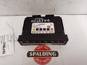
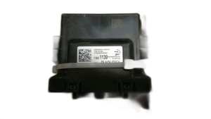
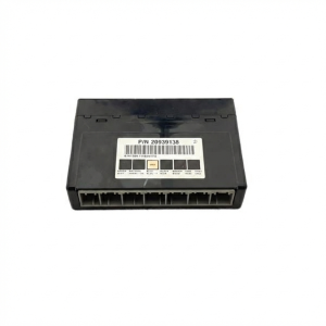
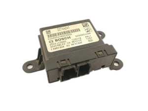
- Electronic Brake Control Module (EBCM)
(OEM #85698746 (supersedes 23154721, 23237319, 84074934, 84074964, 84256796, 84609554))— This is the control module that fails. It is only replaced after all wiring, power, and ground issues have been ruled out. Part number must be matched to the vehicle's VIN and options.
Trusted brands: ACDelco (Genuine GM)
OEM price range: $450-$700
Aftermarket price range: $250-$500 - Wire and Butt Connectors — Needed to repair corroded or broken wires found in the door sill plate harness or frame harness.
Trusted brands: 3M
OEM price range: $10-$30
Aftermarket price range: $5-$20
Related Codes That Often Appear With This One
- U0073 — Control Module Communication Bus 'A' Off. This is a general CAN bus error often set alongside U0121 when a systemic issue like the G218 ground fault occurs.
- U0100 — Lost Communication with ECM/PCM. Indicates a broader CAN bus communication failure, often triggered by the same electrical fault.
- U0101 — Lost Communication with TCM. Indicates a broader CAN bus communication failure. [Bulletin #08-07-30-021H]
- U0140 — Lost Communication with Body Control Module. Since the BCM is the source of the enable circuit and is grounded at G218, this code is a very common partner to U0121.
- U0126, U0131, U0415, U0428 — These are other communication codes for the Steering Angle Sensor, Power Steering Control Module, and others that share the same communication enable circuit (5986) and are often triggered by the same wiring fault under the sill plate. [Bulletin #PIT5457D].
Technical Service Bulletins (TSBs) & Recalls
- PIT5457D: Service ABS/TCS/Power Steering and/or Suspension Message
- 18-NA-161: Intermittent Service Stabilitrak Message, Instrument Panel Cluster Goes Blank, Steering Jerks or Kicks Back
- PIT5405C: (Superseded by 18-NA-161) Steering Jerks Or Kicks Back / Reduced Power Steering Assist / Engine Stall / No Start / Service Stabilitrak
- 08-07-30-021H: Information on Transmission Not Shifting, Instrument Panel Cluster and Radio Inoperative, Door Lock Cycling, Various Communication DTCs
- PIT5599: Information On History DTC U0121 In Front View Camera Module
Platform-Specific Known Issues
- TSB #PIT5457D points to a known issue with the wiring harness under the driver and passenger sill plates being susceptible to corrosion, causing a loss of communication with the EBCM and other modules via the enable circuit (5986).
- TSB #18-NA-161 (superseding PIT5405C) identifies a poor BCM ground at G218, caused by trapped insulation, as a source of numerous communication codes, including U0121, on 2014-2019 models. It also details procedures for voltage drop testing battery cables.
- TSB #08-07-30-021H documents that various communication DTCs, including U0121, can be set due to network issues, leading to symptoms like illuminated warning lamps and transmission shifting problems.
Mechanic-Grade Diagnostic Values
- CAN Bus Network Resistance — expected: ~60 Ohms (measured between Pin 6 and Pin 14 of the OBD-II port with battery disconnected). Failure: A reading of ~120 Ohms suggests an open circuit to one of the two terminating resistors (one is in the EBCM). A reading near 0 Ohms indicates a short between the CAN High and Low wires.
- Communication Enable Circuit (5986) Voltage — expected: Approximately 12V (battery voltage) with the ignition in ACC or ON.. Failure: Low or no voltage indicates an open, short, or high resistance in the circuit, preventing the EBCM from waking up.
- Communication Enable Circuit (5986) Load Test — expected: A 194 incandescent bulb connected between Circuit 5986 at the EBCM connector and a good ground should light up, with at least 11V measured across the bulb.. Failure: If the bulb does not light, or voltage is below 11V, the circuit has high resistance and cannot supply the necessary current to wake the module. The BCM will shut down the circuit if it draws more than 0.88 amps.
- Battery Cable Voltage Drop (Cranking) — expected: Less than 100 mV on the positive side; less than 200 mV on the negative side.. Failure: Higher voltage drops indicate high resistance in the main power or ground cables, which can cause module communication issues.
Scan Tool Commands That Help
- GM GDS2 (Global Diagnostic System 2): Vehicle DTC Information / Full Network Scan — This is the first step to see which other modules are reporting a loss of communication with the EBCM. A long list of 'U' codes points to a network-wide problem (like ground G218 or circuit 5986) rather than an isolated module failure.
- GM GDS2 (Global Diagnostic System 2): Module Diagnostics > EBCM > Data Display — Use this to attempt to view live data (like wheel speeds) from the EBCM. If you can access this screen, it means communication is established at that moment, and the problem may be intermittent or a software issue.
Wiring & Ground Locations
- G218 — On the A-pillar frame, behind the lower driver's side dash/kick panel, often near the A-pillar speaker.. This is the primary ground for the Body Control Module (BCM). Insulation is often trapped under the terminal from the factory, causing a poor connection and leading to a flood of communication codes, including U0121.
- EBCM Connector — On the Electronic Brake Control Module itself, located on the driver's side frame rail.. This is the main connector where all power, ground, and communication lines (CAN bus and Circuit 5986) must be tested to verify the integrity of the circuits leading to the module.
- Splice J365 — In the wiring harness located under the passenger's front sill plate area.. TSB #PIT5457C identifies this splice as a known area where the Communication Enable circuit (5986) can develop an open or high resistance.
- CAN Bus Splice Packs (e.g., JX305, SP205) — Locations vary, but common spots are under the driver's dash above the brake pedal or under the passenger seat. On some models, a terminating resistor is taped to the harness above the spare tire.. These splice packs connect multiple modules to the CAN bus. A problem at the splice pack can take down the entire network. They can be used as a diagnostic point to isolate sections of the network to find a faulty module or wire.
Real Owner Repair Stories
- YouTube user comment (2015 Chevy Silverado (K2XX Platform sibling)) — Multiple warning lights including Stabilitrak, ABS, and trailer brake system. Random electrical issues.
❌ Tried (didn't work) Initial diagnosis pointed to multiple module failures.
✅ What actually fixed it The problem was resolved by locating and cleaning the G218 ground connection under the driver's side dash, which had sound-deadening material caught under it, causing a poor connection.
OEM Part Supersession History
84256780→85698743— Standard part revision and update by the manufacturer.
Model Year Variations Within This Range
- 2014-2016: EBCM Part Number 23377802 (or similar) is common for these early K2XX years.
- 2017-2019: EBCM Part Number 84055067 (or similar) is common for these later K2XX years.
- 2015+: Some models may have an external CAN bus terminating resistor taped to the harness near the rear of the vehicle, above the spare tire area, near the chassis control or fuel pump control module.
Helpful Videos


We Have This Part in Stock

The information in this article is provided for general reference and educational purposes only. Vehicle specifications, procedures, and part compatibility can vary by production date, trim level, and region. Always consult your vehicle's factory service manual and verify part numbers before purchasing or performing repairs. Safety-critical components such as airbags, seat belts, and braking systems should be installed by a qualified professional.
- Chevrolet SILVERADO 3500:
- 🧭 Diagnostic Flowchart
- 🎬 Helpful Videos
- 🛍️ Shop This Part
- What's Unique About the 2013-2019 Chevrolet SILVERADO 3500
- Symptoms You May Notice
- Most Likely Causes
- Rare But Worth Checking
- Diagnosis Steps
- Parts You'll Likely Need
- Related Codes That Often Appear With This One
- Technical Service Bulletins (TSBs) & Recalls
- Platform-Specific Known Issues
- Mechanic-Grade Diagnostic Values
- Scan Tool Commands That Help
- Wiring & Ground Locations
- Real Owner Repair Stories
- OEM Part Supersession History
- Model Year Variations Within This Range
- 🎟️ Get 5% Off