
P0134 on 2005-2016 Scion tC: Causes and Fixes for No O2 Sensor Activity
On the 2005-2016 Scion tC, code P0134 almost always means the upstream Air/Fuel Ratio sensor (Bank 1, Sensor 1) has failed. Replacing this sensor is the most common fix. Expect to pay $70-$150 for an aftermarket part or $190-$220 for an OEM sensor. It is a straightforward DIY job for most.
- P0134 on a Scion tC means the upstream Air/Fuel Ratio sensor (Bank 1, Sensor 1) is not working.
- The most common fix by a wide margin is to replace the sensor itself.
- Before buying a new sensor, it's wise to perform a quick visual inspection of the wiring and check the 'A/F HTR' fuse.
- Use a Denso-branded replacement for best results, as it is the OEM supplier.
- The part number is different for the 1st gen (2.4L) and 2nd gen (2.5L) tC.
What's Unique About the 2005-2016 Scion tC
For the Scion tC, which uses Toyota engineering, the upstream oxygen sensor is a wideband Air/Fuel (A/F) ratio sensor, not a conventional O2 sensor. These are highly accurate but can be more sensitive to age and contamination. The OEM supplier is typically Denso. While the code's cause is overwhelmingly a failed sensor, it's important to use a quality replacement, as these engines' fuel trim systems are precisely calibrated to the OEM sensor's performance. A failure of the sensor's internal heater circuit is a very common reason for the 'no activity' code, as the sensor cannot reach its required operating temperature (around 1200°F) to start sending signals.
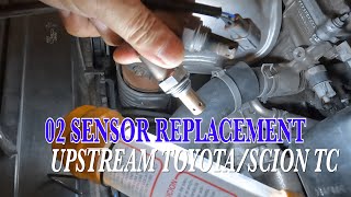
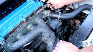
Generation note: This guide covers two generations of the Scion tC. The first generation (2005-2010) uses the 2.4L 2AZ-FE engine. 🎬 Watch: Step-by-step sensor replacement for first generation models. The second generation (2011-2016) uses the 2.5L 2AR-FE engine. 🎬 See this walkthrough for replacing the sensor on 2011-2016 models. The function of the sensor and the meaning of the code are the same for both, but the specific part numbers for the Air/Fuel Ratio sensor are different.
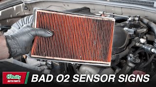
Symptoms You May Notice
- Check Engine Light is on
- Decreased fuel economy
- Rough or uneven idle
- Engine hesitation during acceleration
- Failure to pass an emissions test
- Excessive smoke from exhaust or a smell of rotten eggs
- Replacing the downstream (Bank 1, Sensor 2) oxygen sensor. This code specifically points to the upstream sensor (Sensor 1).
- Cleaning the Mass Airflow (MAF) sensor. While some generic repair videos suggest this, a dirty MAF sensor will not cause a P0134 'no activity' code and is not a valid diagnostic step for this specific fault.
Most Likely Causes
- Failed Upstream Air/Fuel Ratio Sensor (Bank 1, Sensor 1) 🔴 High Probability → Shop Oxygen Sensor A/F sensors are wear items with a typical lifespan of 80,000-100,000 miles. Contamination from oil burning (a known issue on some 2AZ-FE engines) or coolant, and heat cycles eventually cause the internal sensing element or heater circuit to fail. Heater circuit failure is a very common point of failure leading to this code.
How to confirm: Use a scan tool to monitor live data for the B1S1 A/F sensor. A faulty sensor will show a flat, unresponsive voltage/current reading, while a healthy one fluctuates rapidly. You can also test the resistance of the sensor's internal heater circuit with a multimeter after disconnecting it. An open circuit (infinite resistance) or a value outside of the manufacturer's specification (typically a few ohms to tens of ohms when cold) confirms failure. 🎬 Watch: How to test and replace an Air Fuel Ratio sensor.
Typical fix: Replace the upstream Air/Fuel Ratio sensor. Apply anti-seize to the threads of the new sensor if not pre-applied and torque to specification. A special O2 sensor socket is recommended for removal and installation.
Est. part cost: $70-$220 - Damaged Wiring or Connector 🟡 Medium Probability The sensor wiring is located in the hot engine bay and can be susceptible to melting, chafing, or corrosion over time. The plastic connector can become brittle and crack. Rodents can also chew through the wires.
How to confirm: Visually inspect the entire wiring harness from the sensor to the main engine harness. Check for melted plastic, frayed wires, or green corrosion inside the connector pins. Use a multimeter to check for continuity on the signal wires and for 12V power and ground at the connector for the heater circuit with the key on.
Typical fix: Repair the damaged section of wire or replace the connector pigtail. Ensure repairs are properly sealed against heat and moisture.
Est. part cost: $10-$40 - Blown Fuse for Sensor Heater Circuit ⚪ Low Probability A short in the sensor's heater element or its wiring can cause the associated fuse to blow, preventing the sensor from warming up and becoming active. On many 4-cylinder Toyota applications, this fuse also powers other critical components, so a blown fuse may present with other symptoms or a no-start condition.
How to confirm: Consult the owner's manual or the fuse box diagram to locate the fuse for the A/F or O2 sensor heater (often labeled 'A/F HTR'). Visually inspect the fuse or test it for continuity with a multimeter.
Typical fix: Replace the blown fuse. If the new fuse blows immediately, there is a short circuit in the wiring or sensor that must be diagnosed and repaired before proceeding.
Est. part cost: $1-$5
Rare But Worth Checking
- Exhaust Leak: A significant exhaust leak from a cracked manifold or bad gasket before the sensor can draw in outside air, causing the sensor to give strange readings. While this more commonly causes lean codes (P0171), a severe leak could potentially contribute to a no-activity code under certain conditions by preventing the exhaust from getting hot enough or by skewing readings so severely the ECM flags an activity fault.
- Faulty Engine Control Module (ECM): → Shop Engine Control Module (ECM) This is extremely rare. The driver circuit inside the ECM that reads the sensor can fail. This should only be considered after all other possibilities, including the sensor, wiring, fuses, and potential exhaust leaks have been definitively ruled out by a professional.
Diagnosis Steps
- Read the code with an OBD-II scanner to confirm P0134 is present. Note any other codes, especially heater circuit or fuel trim codes, and troubleshoot them first if present.
- Visually inspect the Bank 1, Sensor 1 (upstream) A/F sensor. It is located on the exhaust manifold. Check its wiring harness and connector for any signs of melting, chafing, corrosion, or physical damage.
- Check the fuse for the A/F sensor heater circuit. This is often labeled 'A/F HTR' or similar in the fuse box under the hood.
- Using a scan tool with live data, monitor the voltage for 'AFS B1 S1'. A healthy sensor will show a voltage between 2.8V and 3.8V at idle after warming up. If the value is fixed, flat, or does not change with engine RPM, the sensor is not active.
- If the fuse is good, disconnect the sensor and use a multimeter to test the resistance of the heater circuit on the sensor side. An open circuit (infinite resistance) or a reading outside of a few ohms to tens of ohms confirms the heater inside the sensor has failed and the sensor must be replaced.
- If the heater circuit resistance is good, check for reference voltages at the vehicle-side connector with the Key On, Engine Off. You should measure approximately 3.0V on the AF+ wire and 3.3V on the AF- wire. Lack of these voltages points to a wiring or ECM issue.
- If power, ground, and wiring are all confirmed to be good, and the live data shows no activity, the Air/Fuel Ratio sensor itself has failed and should be replaced.
Parts You'll Likely Need
- Upstream Air/Fuel Ratio Sensor (Bank 1, Sensor 1)
(OEM #89467-33080 (for 2.4L 2AZ-FE, superseded by 89467-06030) / 89467-21020 (for 2.5L 2AR-FE, superseded by 89467-0R050))— This is the component that directly measures exhaust oxygen content and is identified by the code as inactive. It is a wear item and the most common failure point for P0134.
Trusted brands: Denso (OEM), NGK, Walker Products
OEM price range: $195-$220
Aftermarket price range: $70-$150
Related Codes That Often Appear With This One
- P0171 (System Too Lean) or P0172 (System Too Rich) may appear alongside P0134 if the sensor was providing erratic data before failing completely.
- P0031 or P0032 (Heater Circuit Faults) are highly related and point specifically to a failure in the sensor's internal heater, which would also cause a P0134.
Platform-Specific Known Issues
- Oil Consumption on 2AZ-FE: The 2005-2010 Scion tC with the 2AZ-FE engine can be prone to excessive oil consumption. This can lead to premature failure of the A/F sensor due to contamination from burnt oil, poisoning the sensing element. If you have this engine and the P0134 code, it's wise to monitor your oil level closely.
Mechanic-Grade Diagnostic Values
- A/F Sensor Reference Voltage (KOEO) — expected: With sensor unplugged, vehicle-side harness should have ~3.0V on the AF+ wire and ~3.3V on the AF- wire, measured to ground.. Failure: Missing or incorrect voltages point to a wiring issue or a fault in the ECM.
- A/F Sensor Live Data Voltage (Idle) — expected: 2.8V to 3.8V at a stable idle after the engine is fully warmed up.. Failure: A voltage that is flat, unchanging, or stuck at a specific value (e.g., 3.0V or 0V) indicates no activity.
- A/F Sensor Live Data Voltage (Dynamic) — expected: Voltage should drop towards ~2.3V on hard acceleration (rich) and spike towards ~5.0V on abrupt, closed-throttle deceleration (lean).. Failure: Lack of voltage change in response to changing engine load confirms the sensor is inactive.
- A/F Sensor Heater Circuit Resistance — expected: Typically between 0.8 to 15 ohms when measured at the sensor's pins at room temperature. Specific values vary by sensor generation.. Failure: Infinite resistance (Open Loop) indicates a burned-out heater element, which is the most common failure.
Scan Tool Commands That Help
- Toyota Techstream: Active Test: A/F CONTROL — Use this to verify if the sensor is capable of responding. The test allows you to manually command a rich (+25%) or lean (-12.5%) mixture. A healthy sensor's voltage will change accordingly (e.g., to ~2.7V for rich, ~3.7V for lean). If the voltage doesn't change, the sensor is confirmed to be inactive.
- Toyota Techstream: Utility: Learning Value Reset — After replacing the A/F sensor, this function should be used to clear the ECM's long-term fuel trim adaptations that were learned based on the old, faulty sensor. This ensures the ECM starts with a clean slate for the new sensor.
- Manual Procedure: A/F Ratio Self-Learning Reset — As an alternative to Techstream after sensor replacement, warm the engine, turn it off, disconnect the MAF sensor, idle the engine for >5 seconds (will set a MAF code), turn off, reconnect MAF, and clear codes. This forces the ECM to reset fuel learning values.
Wiring & Ground Locations
- ECU Main Ground (2AZ-FE) — On the left side of the cylinder head (driver's side of the engine block).. The ECU, which interprets the A/F sensor signal, relies on this ground. A corroded or loose ground here can cause erratic electrical behavior, potentially leading to incorrect sensor readings or fault codes.
- A/F Sensor ECU Pins (2005 2AZ-FE) — At the Engine Control Module (ECM). Signal wires are at terminals E7-29 (OX1B) and E7-2 (O1B-). Heater circuit is at terminal E7-5 (HA1A).. These are the specific pins to test for continuity or shorts back from the sensor connector, allowing for precise diagnosis of the wiring harness without guesswork.
"I Checked Everything" — The Actual Cause
- This code is almost exclusively electrical in nature, relating to the sensor's internal components or its wiring circuit. A smoke test, which checks for vacuum or exhaust leaks, will typically come back clean and is not a primary diagnostic step for a P0134 'no activity' fault. The problem lies within the sensor's ability to generate a signal, not the composition of the exhaust gas it is measuring.
OEM Part Supersession History
89467-33080→89467-06030— Standard part evolution and consolidation by the manufacturer.89467-21020→89467-0R050— Standard part evolution and consolidation by the manufacturer.
Model Year Variations Within This Range
- 2005-2010 vs 2011-2016: The engine platform changed from the 2.4L 2AZ-FE to the 2.5L 2AR-FE in 2011. This requires a different A/F sensor. The 2AZ-FE uses OEM P/N 89467-33080 (or its successor 89467-06030), corresponding to Denso aftermarket P/N 234-9041. The 2AR-FE uses OEM P/N 89467-21020 (or its successor 89467-0R050), corresponding to Denso aftermarket P/N 234-9114.
Diagnostic Flowchart
Used vs. New Parts: Buying Guide for This Vehicle
When a used part is the smart pick: For this specific repair, a used part is NEVER recommended. The A/F sensor is a wear-and-tear component with a finite lifespan. The cost savings of a used part are minimal compared to the risk of premature failure and repeating the labor.
What to inspect on the donor part:
- Not applicable as used sensors should be avoided.
OEM-only on this vehicle (don't cheap out):
- Engine Control Module (ECM) - In the extremely rare event the ECM is faulty, it should be replaced with a genuine OEM unit or sent to a specialized electronics rebuilder. Do not use a junkyard ECM without proper programming capabilities.
Aftermarket brands forum-validated for this vehicle:
- Denso (OEM supplier)
- NGK / NTK
Brands owners have reported issues with on this vehicle:
- Unbranded 'white-box' sensors from online marketplaces. These often have high failure rates, are dead-on-arrival, or cause performance issues due to not meeting the precise specifications of the original sensor.
Real Owner Stories
Aggregated from forums and TSBs cited above. Mileages and costs reflect what owners reported in those sources.
Scion tC — 117000 miles
Symptoms: Check engine light came on with codes P0134 and P0031 right after an oil change. Using a scan tool app, the owner noted the Bank 1 O2 sensor voltage stayed steady at 0.1V.
What fixed it: The forum thread did not have a confirmed final fix from the owner. They were advised to check for damaged wiring near the oil filter and were considering replacing the O2 sensor.
Source hint: ScionLife.com - O2 sensor codes after instant oil change
1st Gen Scion tC
Symptoms: Check Engine Light on with code P0134.
What fixed it: The issue was resolved immediately by replacing the upstream Air/Fuel Ratio sensor with Denso part #234-9041.
Source hint: ScionLife Forums
2012 Scion tC (2AR-FE)
Symptoms: Check Engine Light on with codes P0134 and P0171.
What fixed it: The problem was fixed by replacing the upstream (front) Air/Fuel Ratio sensor with Denso part #234-9114.
Source hint: ClubSciontC Forums
Related OBD-II Codes
Frequently Asked Questions
My 2008 Scion tC is burning a lot of oil. Could this be related to my P0134 code?
What is the correct replacement part number for the upstream A/F sensor on my first-generation (2005-2010) tC?
I have a 2012 Scion tC. Is the A/F sensor part number the same as the first generation?
Where exactly is the Bank 1 Sensor 1 located on my Scion tC?
What voltage should I look for on my scan tool to confirm the A/F sensor is working correctly?
I found a blown 'A/F HTR' fuse. If I replace it and it blows again, what does that mean?
Helpful Videos

We Have This Part in Stock


The information in this article is provided for general reference and educational purposes only. Vehicle specifications, procedures, and part compatibility can vary by production date, trim level, and region. Always consult your vehicle's factory service manual and verify part numbers before purchasing or performing repairs. Safety-critical components such as airbags, seat belts, and braking systems should be installed by a qualified professional.
- Scion tC:
- 🧭 Diagnostic Flowchart
- 🎬 Helpful Videos
- 🛍️ Shop This Part
- What's Unique About the 2005-2016 Scion tC
- Symptoms You May Notice
- Most Likely Causes
- Rare But Worth Checking
- Diagnosis Steps
- Parts You'll Likely Need
- Related Codes That Often Appear With This One
- Platform-Specific Known Issues
- Mechanic-Grade Diagnostic Values
- Scan Tool Commands That Help
- Wiring & Ground Locations
- "I Checked Everything" — The Actual Cause
- OEM Part Supersession History
- Model Year Variations Within This Range
- Used vs. New Parts: Buying Guide for This Vehicle
- Real Owner Stories
- Scion tC — 117000 miles
- 1st Gen Scion tC
- 2012 Scion tC (2AR-FE)
- Related OBD-II Codes
- Frequently Asked Questions
- 🎟️ Get 5% Off