
P0135 on 2006-2012 Toyota RAV4: O2 Sensor Heater Circuit Causes and Fixes
This code means the heater inside the upstream Air/Fuel ratio sensor has failed. On the 2006-2012 RAV4, this is almost always fixed by replacing the Bank 1, Sensor 1 A/F sensor. On the 2.4L and 2.5L engines, this is an easy repair. On the 3.5L V6, the sensor is on the firewall side and is more difficult to access. Expect to pay $120-$190 for an OEM-quality part (Denso is the original manufacturer) and about 0.5-1.5 hours of labor.
- P0135 specifically points to a failure in the heater circuit of the upstream Air/Fuel Ratio sensor in Bank 1.
- The most common cause by a wide margin is the sensor itself failing. Diagnosis is straightforward by checking the heater's resistance, which should be between 1.8-3.4 ohms.
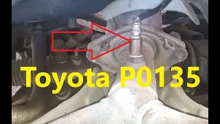
- For the 2.4L/2.5L engine, the sensor is on the front of the engine and is an easy DIY fix. For the 3.5L V6, it's the harder-to-reach sensor on the firewall side, which may require more extensive disassembly.
- Using an OEM part from Denso (or the direct Denso aftermarket equivalent like 234-9049) is highly recommended to ensure compatibility and longevity.
- This is a DIY-friendly repair that requires an O2 sensor socket but can save significant labor costs, especially on the 4-cylinder models.
What's Unique About the 2006-2012 Toyota RAV4
The 2006-2012 (XA30 generation) RAV4 uses Denso wideband Air/Fuel ratio sensors for upstream fuel control, which are reliable but whose internal heater elements are a common failure point over time. The failure is almost always the sensor itself, not the vehicle's wiring or fuses. The key difference for this platform is identifying the correct 'Bank 1, Sensor 1': on the 2.4L (2AZ-FE) and 2.5L (2AR-FE) 4-cylinder engines, it's the easily accessible sensor in the exhaust manifold. 🎬 Watch: This easy DIY walkthrough for 4-cylinder sensor replacement. On the 3.5L (2GR-FE) V6, 'Bank 1' is the cylinder bank against the firewall, making Sensor 1 much less accessible and often requiring removal of the cowl and intake components for access.
Symptoms You May Notice
- Check Engine Light is on.
- Slightly decreased fuel economy.
- Failure to pass an emissions test.
- Rough idle on cold starts (less common).
- Black smoke or bad smell from exhaust (rare).
- Replacing the wrong oxygen sensor (e.g., the downstream Sensor 2 or the Bank 2 sensor on V6 models). P0135 is specific to Bank 1, Sensor 1.
- Assuming the sensor is bad without testing. While it is the most likely cause, a 5-minute resistance check can prevent replacing a good part.
- Using a cheap, universal-style sensor that requires splicing wires. Poor connections from splicing can cause the code to return.
Most Likely Causes
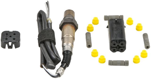
- Failed Air/Fuel Ratio Sensor Heater Element 🔴 High Probability → Shop Oxygen Sensor The internal heating element within the sensor is a known wear item and the most common cause for this code on Toyotas. After many heat cycles, the filament simply burns out or breaks, creating an open circuit.
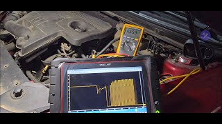
How to confirm: Disconnect the sensor and measure the resistance between the two heater pins on the sensor side (often the two same-colored wires, e.g., black). A good heater will have low resistance, typically between 1.8 and 3.4 Ohms at 68°F (20°C). An open circuit (infinite resistance, or 'OL' on a multimeter) confirms the heater has failed.
Typical fix: Replace the Air/Fuel Ratio Sensor (Bank 1, Sensor 1).
Est. part cost: $120-$190 - Blown A/F Heater Fuse or Relay ⚪ Low Probability While less common than sensor failure, a power surge or a short circuit in the old sensor or wiring can blow the fuse that protects the heater circuit.
How to confirm: Locate the fuse box in the engine bay. Check the 15A fuse labeled 'A/F HTR'. Visually inspect the fuse or use a multimeter to test for continuity. Also locate the 'A/F HTR' relay in the same box and test or swap it with a known-good relay.
Typical fix: Replace the blown fuse or faulty relay. If the fuse blows again immediately, there is a short circuit in the wiring or the new sensor itself that needs to be diagnosed.
Est. part cost: $1-$20 - Damaged Wiring or Connector ⚪ Low Probability The wiring harness leading to the sensor is exposed to high heat and potential road debris, which can cause wires to melt, fray, or break over time. The connector pins can also corrode from moisture.
How to confirm: Visually inspect the wiring harness from the sensor up to the engine. Look for any signs of melting, chafing, or broken wires. Unplug the connector and check for corrosion, moisture, or bent/damaged pins.
Typical fix: Repair the damaged section of wiring or replace the connector pigtail.
Est. part cost: $10-$30
Rare But Worth Checking
- Faulty Engine Control Module (ECM): → Shop Engine Control Module (ECM) This is extremely rare. The ECM should only be considered after all other possibilities (sensor, fuse, wiring) have been definitively ruled out. A failure of the internal ECM driver for the heater circuit is the specific fault.
Diagnosis Steps
- Verify the code with an OBD-II scanner. Confirm it is P0135 and no other related codes are present.
- Identify the correct sensor. For the 2.4L 2AZ-FE and 2.5L 2AR-FE, Bank 1 Sensor 1 is the upstream sensor in the exhaust manifold, easily visible from the front of the engine bay. For the 3.5L 2GR-FE, Bank 1 is the cylinder bank against the firewall, and Sensor 1 is the upstream sensor in that manifold, which is difficult to see and reach.
- Inspect the wiring and connector. Check for any visible damage, melting, or corrosion between the sensor and where it connects to the main engine harness.
- Check the A/F heater fuse and relay. Locate the engine compartment fuse/relay box and check the 15A 'A/F HTR' fuse and the 'A/F HTR' relay.
- Test the sensor's heater circuit. Disconnect the sensor and use a multimeter to measure the resistance across the two heater pins 🎬 See how to test oxygen sensor heater circuits with a multimeter. on the sensor itself. A reading of 'OL' or infinite resistance indicates a failed heater element. The resistance should be low, typically between 1.8 and 3.4 ohms when the sensor is at room temperature.
- Test for power at the harness connector. With the key in the 'ON' position (engine off), use a multimeter to verify that you have battery voltage (9-14V) at the harness-side connector pin for the heater. The other pin is the control circuit from the ECM, which provides a duty-cycled ground.
- If the sensor heater has correct resistance and the harness has power, the problem is intermittent, a poor connection, or, in very rare cases, the ECM driver circuit.
Parts You'll Likely Need
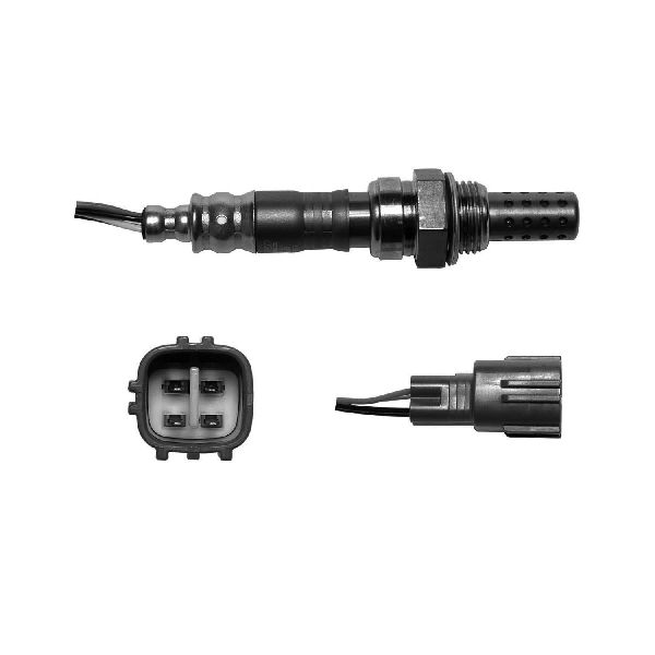
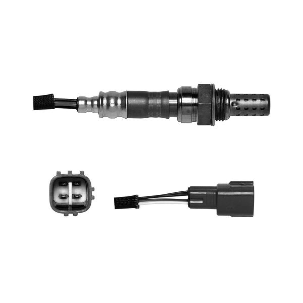
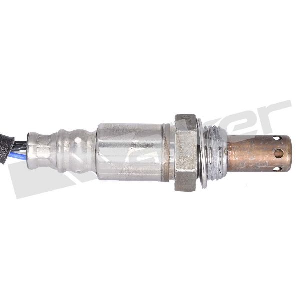
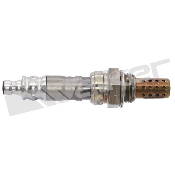
- Air/Fuel Ratio Sensor (Bank 1, Sensor 1)
(OEM #89467-42120 (for 2.5L 2AR-FE), 89467-42090 (for 2.4L 2AZ-FE), 89467-0E010 (for 3.5L 2GR-FE, Bank 1))— This is the component whose internal heater circuit has failed, triggering the P0135 code. It is the direct fix in over 95% of cases. 🎬 Watch: A breakdown of causes and fixes for the P0135 code.
Trusted brands: Denso (OEM), Denso 234-9049 (Aftermarket equivalent for 2.4L/2.5L)
OEM price range: $180-$250
Aftermarket price range: $120-$190
Platform-Specific Known Issues
- V6 (2GR-FE) Sensor Accessibility: Replacing Bank 1, Sensor 1 on the 3.5L V6 is significantly more difficult than on the 4-cylinder models. The sensor is located on the rear exhaust manifold (firewall side), and access is heavily restricted. Mechanics and DIYers often need to remove the plastic cowl panel at the base of the windshield and sometimes the intake manifold plenum to gain enough clearance to reach the sensor and its connector. This increases labor time from ~30 minutes to 1.5-2.0 hours.
Mechanic-Grade Diagnostic Values
- A/F Sensor Heater Resistance (at sensor connector) — expected: 1.8 to 3.4 Ohms at 68°F (20°C). Failure: Open circuit ('OL' on multimeter) or resistance far outside the specified range.
- A/F Sensor Heater Voltage at Harness Connector (2AZ-FE) — expected: 9 to 14 V (Key On, Engine Off) between pin HA1A (ECM connector B30, pin 109) and chassis ground.. Failure: 0V indicates a blown fuse, bad relay, or wiring issue. Voltage should drop below 3.0V at idle as the ECM controls the circuit.
- A/F Sensor Heater Voltage at Harness Connector (2GR-FE) — expected: 9 to 14 V (Key On, Engine Off) between heater power pin and chassis ground.. Failure: 0V indicates a problem in the power supply side (fuse, relay, wiring).
- Mode $06 Data for O2 Heater Monitor — expected: Test value for TID $81, CID $01 should be within the MIN and MAX limits specified by the ECM.. Failure: A test value that is outside the MIN/MAX threshold confirms the heater circuit performance is out of range, triggering P0135.
Hidden / Shadow Codes Worth Checking
- Mode $06, TID $81, CID $01: This is not a separate trouble code, but the result of the onboard diagnostic monitor for the Bank 1 Sensor 1 heater. It shows the raw test value (e.g., current draw or resistance) measured by the ECM, along with the minimum and maximum acceptable values. A 'FAIL' status on this monitor test is what triggers the P0135 code. (see via A professional scan tool capable of displaying Mode $06 data.)
Scan Tool Commands That Help
- Toyota Techstream: Active Test: 'Control the A/F Sensor Heater (Bank 1, Sensor 1)' — This is used when the sensor's heater resistance tests good, but you suspect a wiring or ECM issue. The command forces the heater circuit ON. You can then monitor the current draw or sensor temperature to confirm if the ECM, relay, and wiring are capable of activating the heater. If the command works but the code persists, it points strongly to an intermittent sensor or connection issue.
Wiring & Ground Locations
- A/F HTR Relay — In the main engine compartment fuse/relay box (Engine Room R/B No.1).. This relay provides power to the A/F sensor's heater element. A failure of this relay will cut power and trigger P0135.
- Ground Point EC (2AZ-FE) — On the left rear of the cylinder head.. This is a primary ground point for the engine harness, which includes the A/F sensor circuits. A loose or corroded ground here can cause erratic sensor readings and faults.
- ECM Heater Ground Pin (2AZ-FE) — Pin E04 (ECM connector B30, pin 46).. The ECM controls the heater by duty-cycling the ground connection. Testing for continuity between the sensor harness and this pin can diagnose a broken wire, while testing voltage at this pin can help diagnose a faulty ECM driver.
- V6 Engine Ground Straps — Multiple straps connect the engine block and cylinder heads to the chassis/firewall. One key location is from the rear cylinder head (Bank 1) to the firewall.. On the 2GR-FE, ensuring the Bank 1 cylinder head has a clean, tight ground connection to the chassis is critical, as this bank is electrically further from the battery ground.
Real Owner Repair Stories
- Reddit r/MechanicAdvice (Honda Civic (similar circuit design)) — P0135 code returned immediately after replacing the Bank 1 Sensor 1.
❌ Tried (didn't work) Replacing the O2 sensor.
✅ What actually fixed it The old sensor had failed with an internal short, which blew the heater circuit fuse. The fuse was not checked initially. Replacing the fuse after the new sensor was installed resolved the code. - Online Forum User (Vehicle unspecified, common issue) — Intermittent P0135 error after replacing the sensor with a universal, splice-in type.
❌ Tried (didn't work) Clearing the code, which would return after a few drive cycles.
✅ What actually fixed it The user cut out the spliced connections and re-did them, ensuring a perfect, waterproof seal. The root cause was a poor connection in the user-spliced wiring that had high resistance, mimicking a failed heater element. The ultimate recommendation was to always use a direct-fit sensor with an OEM connector.
OEM Part Supersession History
89467-42090→89467-42090 (current)— Part number has remained stable for the 2.4L 2AZ-FE application.89467-42120→89467-42120 (current)— Part number has remained stable for the 2.5L 2AR-FE application.
Model Year Variations Within This Range
- 2006-2008: Uses the 2.4L 2AZ-FE engine. The correct B1S1 A/F sensor is Toyota P/N 89467-42090.
- 2009-2012: Uses the updated 2.5L 2AR-FE engine. The correct B1S1 A/F sensor is Toyota P/N 89467-42120.
Diagnostic Flowchart
Other Known Issues on This Vehicle
Issues unrelated to this code that are worth knowing about as an owner of this generation:
- Excessive Oil Consumption (2.4L 2AZ-FE) 🔴 High — Common after 60,000-100,000 miles on 2006-2008 models. Caused by faulty piston ring design. (Ref: TSB T-SB-0094-11 and Warranty Enhancement Program ZE7 addressed this issue, but have since expired.)
- Steering Intermediate Shaft Clunk 🟠 Medium — Common on 2006-2008 models, causing a clunk or pop noise when turning the steering wheel at low speeds. (Ref: TSB T-SB-0318-08 was issued with an updated part to fix the noise.)
- VVT-i Oil Line Rupture (3.5L 2GR-FE) 🔴 High — Affects early V6 models (2006-2009). A rubber section of the oil line can burst, causing rapid, catastrophic oil loss and engine failure. (Ref: A Limited Service Campaign (LSC 90K) was issued to replace the rubber hose with an all-metal line.)
- Water Pump Failure (3.5L 2GR-FE) 🟠 Medium — A relatively common failure item, often showing signs of a slow pink coolant leak from the weep hole. Can be expensive to replace due to labor.
- Ignition Coil Failure 🟡 Low — Individual ignition coils can fail, causing a misfire (flashing check engine light) and rough running. Relatively common but inexpensive and easy to fix.
Used vs. New Parts: Buying Guide for This Vehicle
When a used part is the smart pick: For this repair, a used part is almost never a smart choice. The only exception would be sourcing a used wiring harness connector pigtail if the original was physically damaged.
Donor-vehicle mileage cap: roughly under 50000 miles for the part to have meaningful remaining life.
What to inspect on the donor part:
- For a connector pigtail, inspect for brittle plastic, corrosion on pins, or any signs of melting.
- Ensure the locking tab on the connector is intact and functional.
OEM-only on this vehicle (don't cheap out):
- Air/Fuel Ratio Sensor - This is a critical emissions and engine management component that is also a wear item. Using a new OEM (Toyota-branded) or OEM-supplier (Denso) part is essential for proper function and longevity.
Aftermarket brands forum-validated for this vehicle:
- Denso (This is the Original Equipment Manufacturer)
Brands owners have reported issues with on this vehicle:
- Bosch: While a quality brand for European vehicles, forum consensus frequently reports that Bosch O2/AF sensors can have compatibility issues with Toyota engine management systems, sometimes not performing correctly or failing prematurely.
- No-Name/Generic Brands: Inexpensive sensors from online marketplaces are notorious for being out-of-spec on arrival or failing very quickly, causing the code to return.
Real Owner Stories
Aggregated from forums and TSBs cited above. Mileages and costs reflect what owners reported in those sources.
2007 Toyota RAV4 V6 3.5L
Symptoms: Owners discussed the challenge of the rear sensor replacement, with some opting to pay a mechanic due to the tight access.
What fixed it: Replacement of the Bank 1, Sensor 1 A/F sensor, often using crowsfoot O2 sensor sockets to reach the sensor from above.
Source hint: RAV4World Thread 'P0135 on 2007 V6'
2006-2012 Toyota RAV4 2.4L — ~30 miles
Symptoms: Check engine light with code P0135.
What fixed it: Replacement of the sensor with Denso part 234-9049 in under 30 minutes.
Source hint: ToyotaNation Thread 'RAV4 P0135 fix'
Related OBD-II Codes
Frequently Asked Questions
Which specific replacement part is recommended for the P0135 code on my RAV4?
Is the P0135 repair more difficult on the V6 RAV4 compared to the 4-cylinder model?
Where is the fuse for the Air/Fuel sensor heater located on a 2006-2012 RAV4?
What should the resistance be for a healthy A/F sensor heater on this vehicle?
Could my RAV4's excessive oil consumption be related to the P0135 code?
Does the V6 oil line rupture issue affect the A/F sensor?
Helpful Videos


We Have This Part in Stock


The information in this article is provided for general reference and educational purposes only. Vehicle specifications, procedures, and part compatibility can vary by production date, trim level, and region. Always consult your vehicle's factory service manual and verify part numbers before purchasing or performing repairs. Safety-critical components such as airbags, seat belts, and braking systems should be installed by a qualified professional.
- Toyota RAV4:
- 🧭 Diagnostic Flowchart
- 🎬 Helpful Videos
- 🛍️ Shop This Part
- What's Unique About the 2006-2012 Toyota RAV4
- Symptoms You May Notice
- Most Likely Causes
- Rare But Worth Checking
- Diagnosis Steps
- Parts You'll Likely Need
- Platform-Specific Known Issues
- Mechanic-Grade Diagnostic Values
- Hidden / Shadow Codes Worth Checking
- Scan Tool Commands That Help
- Wiring & Ground Locations
- Real Owner Repair Stories
- OEM Part Supersession History
- Model Year Variations Within This Range
- Other Known Issues on This Vehicle
- Used vs. New Parts: Buying Guide for This Vehicle
- Real Owner Stories
- 2007 Toyota RAV4 V6 3.5L
- 2006-2012 Toyota RAV4 2.4L — ~30 miles
- Related OBD-II Codes
- Frequently Asked Questions
- 🎟️ Get 5% Off