
P0500 on 1995-2005 Chevrolet Blazer: Causes and Fixes for Vehicle Speed Sensor Malfunction
On a 1995-2005 Chevy Blazer, code P0500 almost always means the Vehicle Speed Sensor (VSS) has failed. This causes an erratic speedometer, poor transmission shifting, and no cruise control. The sensor is located on the transmission tailshaft (2WD) or transfer case (4WD). Replacing it is a simple DIY job costing around $20-$60 for the part.
- P0500 on a Blazer is almost certainly a bad Vehicle Speed Sensor (VSS).
- Symptoms are severe and affect drivability, including harsh shifting and an unreliable speedometer.
- The fix is usually cheap and easy: replace the VSS. It's held by one bolt on either the transmission (2WD) or transfer case (4WD).
- Always check the VSS connector and wiring for damage before replacing the sensor.
- Verify you have the correct part, especially for 4WD models, as it can vary by transfer case. You may need to remove a small cover plate to access it on 4x4s.
What's Unique About the 1995-2005 Chevrolet Blazer
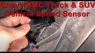
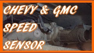
The key difference on the second-generation Blazer is the location of the VSS, which depends on the drivetrain. On 2-wheel drive (2WD) models, the sensor is on the driver's side of the 4L60E automatic transmission's tailshaft housing. On 4-wheel drive (4WD) models, it is located on the output housing of the transfer case, also typically on the driver's side. Different transfer cases, like the 3-button NP233 (part-time 4WD) versus the 4-button NP236 (Auto 4WD), can use slightly different sensors or have the sensor in a location that is harder to access, sometimes requiring removal of a small cover plate. 🎬 Watch: 4WD Blazer transfer case speed sensor replacement Verifying the correct part by visual inspection is crucial. For early models (approx. 1995-1997), the VSS signal is first sent to a VSS buffer module (also called a DRAC) which then converts and distributes the signal to the PCM and instrument cluster; later models integrated this function into the PCM.
Symptoms You May Notice
- Check Engine Light is on
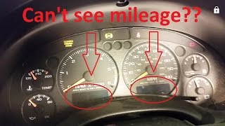
- Erratic speedometer (needle jumps around or drops to zero)
- Harsh, delayed, or incorrect automatic transmission shifting
- Transmission may get stuck in a low gear (limp mode)
- Cruise control does not work
- Odometer may not function
- ABS light may illuminate, sometimes accompanied by the E-Brake light 🎬 See how a bad speed sensor triggers these exact symptoms
- Replacing the transmission or rebuilding it due to harsh shifting, when the issue is only a cheap and simple sensor.
- Replacing the ABS wheel speed sensors. While these also measure speed, the P0500 code on a Blazer is triggered by the primary VSS on the transmission or transfer case, not the ABS sensors at the wheels.
Most Likely Causes
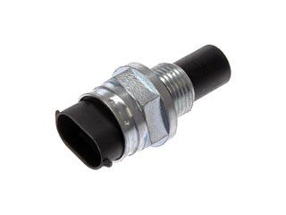
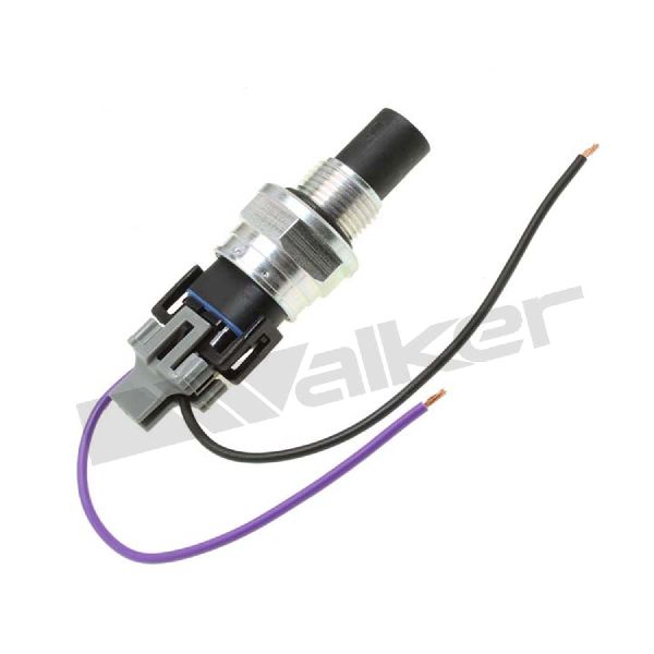
- Failed Vehicle Speed Sensor (VSS) 🔴 High Probability → Shop Drive Shaft Sensor The sensor is a common failure point due to age, heat exposure from the transmission/transfer case, and potential contamination from fluid leaks. It's an electronic part in a harsh environment that wears out over time.
How to confirm: After checking wiring, test the sensor's output signal with a multimeter set to AC volts or a scan tool's live data while spinning the wheels. A lack of signal or an erratic signal indicates a failed sensor. A new sensor should have a resistance of around 1250 ohms. Many owners report simply replacing the sensor as the first step due to its high failure rate and low cost.
Typical fix: Replace the Vehicle Speed Sensor. It is typically held in by a single 5/16" or 8mm bolt.
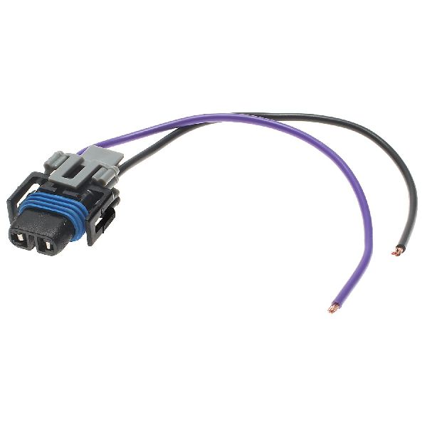
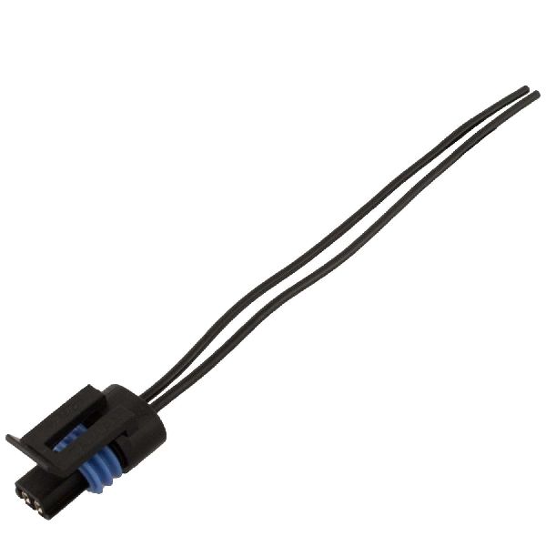
Est. part cost: $20-$60 - Damaged Wiring or Connector 🟡 Medium Probability The wiring harness is located under the vehicle and is exposed to road debris, moisture, and heat from the exhaust and transmission, which can cause corrosion, fraying, or breaks over time. The connector pins are particularly susceptible to corrosion and the wires can break right at the back of the connector.
How to confirm: Visually inspect the wiring harness and connector leading to the VSS for any signs of damage, corrosion, or loose pins. Wiggle the connector and wires while monitoring the speedometer or scan tool data to check for intermittent faults. Pay close attention to where the harness may rub against the frame or exhaust components.
Typical fix: Repair the broken section of wire or replace the connector pigtail. Clean corroded pins with electrical contact cleaner.
Est. part cost: $10-$30
Rare But Worth Checking
- Faulty Instrument Cluster: → Shop Instrument Cluster If the VSS and wiring are good and a scan tool shows a correct speed signal being sent to the PCM, but the speedometer itself isn't working, the problem may lie within the instrument cluster's internal circuitry or a failed stepper motor. This is a known issue on some GM vehicles of this era, often due to cold or cracked solder joints on the circuit board. 🎬 Watch: How to repair a failing GM instrument cluster
- Failed PCM: This is extremely rare. The Powertrain Control Module (PCM) itself could be faulty and unable to process the VSS signal. This should only be considered after all other possibilities have been exhaustively ruled out.
- Grounding Issues: A poor ground connection at the back of the cylinder heads (G104, G114) can cause various electrical gremlins, including erratic sensor readings. Ensure these grounds are clean and tight.
- Failed VSS Buffer / DRAC Module (1995-1997): On early models, the VSS signal goes to a separate buffer module (Digital Ratio Adapter Controller) before the PCM. Failure of this white, box-like module, often located near the PCM, will cause a loss of speed signal even with a good sensor.
Diagnosis Steps
- Read the code with an OBD-II scanner to confirm P0500 is present. Note any other codes, especially ABS or transmission codes.
- Visually inspect the VSS wiring harness and connector. Look for obvious signs of damage, such as frayed wires, melting near the exhaust, or green corrosion in the connector pins.
- Use a scan tool to monitor the vehicle speed data PID from the PCM. If the reading is 0 MPH while driving, or if it's erratic and doesn't match the actual speed, the signal is lost or corrupted.
- If the wiring looks good, test the sensor. Disconnect the sensor and use a multimeter set to Ohms. A good sensor should have a resistance between 190-250 ohms per some general guides, but forum users have reported a new sensor for a Blazer measuring around 1250 ohms. An open circuit (OL) indicates a failed sensor.
- Reconnect the sensor and test the signal output. With the drive wheels raised safely off the ground, connect a multimeter set to AC Volts to the two pins of the sensor. As you spin the wheels, you should see an AC voltage that increases smoothly with speed. A lack of a fluctuating AC signal indicates a bad sensor.
- If the sensor produces a good signal at the sensor connector, but the scan tool shows no speed, the problem is in the wiring between the sensor and the PCM (or VSS Buffer on early models). Check for continuity on the signal and ground wires.
- If the scan tool shows a correct speed signal, but the speedometer doesn't work, the issue is likely the instrument cluster itself.
Parts You'll Likely Need
- Vehicle Speed Sensor (VSS)
(OEM #15547452 (Verify application, primarily for 2WD))— This is the most common cause of the P0500 code. The sensor itself fails internally from age and heat cycles.
Trusted brands: ACDelco (GM Genuine: 15547452, ACDelco Gold/Professional: 213-197), Delphi, Standard Motor Products (SMP) (e.g., SC13), Carquest (e.g., SDC3665)
OEM price range: $40-$70
Aftermarket price range: $20-$50
Related Codes That Often Appear With This One
- P0720 - Output Speed Sensor Circuit Malfunction (less common, but related)
- ABS-related codes if the VSS signal loss impacts the ABS module's calculations.
Platform-Specific Known Issues
- On 4WD models, it is critical to identify the correct transfer case (e.g., NP233, NP236) to get the right speed sensor, as they can differ.
- Corrosion on the connector pins is common due to its exposed location under the vehicle.
- On some 4WD models, the VSS is tucked behind a small skid plate or cover on the transfer case that must be removed for access (held by ~5 bolts).
Mechanic-Grade Diagnostic Values
- Vehicle Speed Sensor (VSS) Resistance — expected: ~1250 Ohms (for a new sensor). Failure: An open circuit (OL) or a reading significantly different from the expected value. An old sensor measured at 1600 Ohms before failing.
- Vehicle Speed Sensor (VSS) AC Voltage Output — expected: A fluctuating AC voltage that increases in both voltage and frequency as the wheel is spun.. Failure: No AC voltage signal, or a signal that does not change with wheel speed.
- VSS Signal Frequency at PCM/ECU — expected: A regular pulse frequency that increases with vehicle speed, typically in the range of 0-800 Hz.. Failure: No pulse signal, or an erratic/inconsistent signal that doesn't correlate with speed.
Scan Tool Commands That Help
- Tech2 / Professional Scan Tool: Live Data - Vehicle Speed (VSS) — This is the primary method to confirm what the PCM is seeing. Monitor this PID while driving to see if the speed reading is 0, erratic, or doesn't match the actual vehicle speed. This helps differentiate a sensor/wiring issue from an instrument cluster problem.
Wiring & Ground Locations
- VSS Connector — On the tailshaft of the transmission (2WD) or transfer case (4WD), driver's side.. This is the primary connection point for the sensor. The connector itself and the wires leading into it are a common failure point due to exposure to heat, moisture, and vibration, often breaking internally.
- G114 / G104 — Bolted to the rear of the driver's side (G114) and passenger's side (G104) cylinder heads.. These are major engine and sensor ground points. A loose or corroded connection here can cause a floating ground, leading to erratic readings from various sensors, including the VSS.
- VSS Signal Wires — Typically a twisted pair of wires (often purple and yellow) running from the VSS to the PCM (or DRAC module on older models).. These two wires carry the raw AC signal from the sensor. Any breaks, shorts, or chafing along this harness will corrupt or eliminate the signal, causing the P0500 code.
Real Owner Repair Stories
- BlazerForum.com user 'fixmycar' (1996 Chevrolet Blazer) — Speedometer reading 0, improper shifting, P0502 code (related to P0500).
❌ Tried (didn't work) Initially measured sensor resistance at 1600 ohms and thought it was okay., Checked wiring to the VCM and found no signal, leading back to the sensor.
✅ What actually fixed it The original VSS had failed, showing an open circuit on a re-test. A new sensor, which measured 1250 ohms before installation, resolved the shifting and speedometer issues. - YouTube user 'mjcrawf' (Vehicle not specified, but common GM repair) — P0500 code, likely speedometer/shifting issues.
❌ Tried (didn't work) Soldering the broken wires back onto the original connector clip, which failed again shortly after.
✅ What actually fixed it The wires had completely broken off the back of the VSS connector. The final fix was replacing the entire connector with a new pigtail, which was then spliced into the vehicle's harness. - BlazerForum.com user 'frank70' (1998 4WD Blazer) — Erratic speedometer, transmission won't shift out of first gear.
❌ Tried (didn't work) Replacing the Vehicle Speed Sensor (VSS) on the transfer case did not fix the problem.
✅ What actually fixed it The user was advised that if a scan tool shows a consistent VSS signal being received by the computer, the problem is likely a bad stepper motor or cold solder joint within the instrument gauge cluster itself. This pointed to the cluster as the next logical diagnostic step.
OEM Part Supersession History
15547452→ACDelco 213-197— Standard part lifecycle replacement and consolidation.
Heads up: While 213-197 is a common replacement, it's crucial to verify the application based on 2WD vs 4WD and the specific transfer case, as several different VSS sensors were used across the 1995-2005 range. Visual match is recommended.
Model Year Variations Within This Range
- 1995-1997: These earlier models use a separate VSS Buffer, also known as a DRAC (Digital Ratio Adapter Controller), located between the VSS and the PCM. This module can be a point of failure, whereas 1998+ models have this function integrated into the PCM.
- 1998-2005: These models feature a redesigned dashboard and instrument cluster. The clusters are not directly interchangeable with pre-1998 models without wiring modifications. A faulty cluster in these years is a common cause of a dead speedometer even when the PCM receives a valid speed signal.
Diagnostic Flowchart
Other Known Issues on This Vehicle
Issues unrelated to this code that are worth knowing about as an owner of this generation:
- Fuel Pump Failure 🔴 High — Extremely common. Often fails between 100k-150k miles, causing a no-start or stalling condition. Access requires dropping the fuel tank.
- Lower Intake Manifold (LIM) Gasket Leak 🔴 High — Very common on the 4.3L V6. The original plastic-carrier gaskets degrade, causing coolant to leak externally or, more dangerously, internally into the oil.
- Premature Ball Joint Wear 🔴 High — Common on 2WD and 4WD models, leading to front-end clunks, poor alignment, and tire wear. Can result in catastrophic failure if ignored. (Ref: NHTSA Recall 03V-328 (GM #03044) was issued for some 1999-2000 models for lower ball joint separation risk.)
- 4WD Vacuum Actuator Failure 🟠 Medium — Common issue where the 4WD will not engage. Usually caused by a leaking vacuum line under the battery tray or a failed vacuum actuator diaphragm on the front axle.
- Sagging Doors (Worn Hinge Pins & Bushings) 🟡 Low — Almost universal on high-mileage or frequently used vehicles. The door drops when opened, making it difficult to close and causing wind noise.
Used vs. New Parts: Buying Guide for This Vehicle
When a used part is the smart pick: A used part is a smart choice for the Instrument Cluster or a wiring connector pigtail. A complete, working used cluster from a junkyard is often the most cost-effective fix for a failed speedometer gauge or stepper motor. A used pigtail is perfect for repairing a damaged connector.
Donor-vehicle mileage cap: roughly under 150000 miles for the part to have meaningful remaining life.
What to inspect on the donor part:
- For an Instrument Cluster: Check for a clear lens with no deep scratches. Ensure the donor vehicle's mileage is displayed on the odometer to verify it powers on.
- For a Connector Pigtail: Ensure there are at least 4-6 inches of wire attached. Inspect the connector for any cracks, and check that the locking tab is intact. The wires should be flexible, not brittle.
Aftermarket brands forum-validated for this vehicle:
- For VSS: ACDelco (GM Original), Delphi, Standard Motor Products (SMP) are considered reliable.
- For Instrument Cluster Repair: Services like CBoardRepair specialize in rebuilding these clusters with upgraded components and a lifetime warranty.
Brands owners have reported issues with on this vehicle:
- Unnamed, 'white box' vehicle speed sensors from online marketplaces may have poor reliability and are best avoided, as the labor to re-install the part outweighs the small cost savings.
Real Owner Stories
Aggregated from forums and TSBs cited above. Mileages and costs reflect what owners reported in those sources.
2000 Chevrolet Blazer
Symptoms: ABS light never went off, the speedometer remained at 0, and the transmission wouldn't automatically shift for the first 200 feet of driving.
What fixed it: The issue was intermittent but related to the VSS signal; cleaning the sensor or replacing it is the standard resolution for these symptoms.
Source hint: Blazer Forum owner report
1999 Chevy Blazer 4x4
Symptoms: ABS engaged at stop, transmission in limp mode, and no speedometer function.
What fixed it: Replacement of the VSS located behind a 5-bolt cover on the transfer case.
Source hint: Reddit.com /r/Cartalk thread title '1999 Chevy Blazer 4x4 need help locating speed sensor'
1998 Chevrolet Blazer 4WD
Symptoms: Speedometer not working; PCM was receiving a good signal but the gauge remained at zero.
What fixed it: The issue was identified as a bad stepper motor in the instrument cluster rather than the VSS itself.
Source hint: BlazerForum.com thread title 'VSS/ speedometer'
Related OBD-II Codes
Frequently Asked Questions
Where is the Vehicle Speed Sensor located on my 4WD 1999 Blazer?
My 2000 Blazer has an ABS light and the speedometer is at zero; could this be the VSS?
What should the resistance of a new VSS be for a Chevrolet Blazer?
If my scan tool shows the correct speed but my speedometer is dead, is the VSS still the problem?
Are there any recalls for the front end of my 1999-2000 Blazer that I should know about?
Why does my Blazer shift harshly or get stuck in a low gear when the Check Engine Light comes on for P0500?
Helpful Videos
We Have This Part in Stock


The information in this article is provided for general reference and educational purposes only. Vehicle specifications, procedures, and part compatibility can vary by production date, trim level, and region. Always consult your vehicle's factory service manual and verify part numbers before purchasing or performing repairs. Safety-critical components such as airbags, seat belts, and braking systems should be installed by a qualified professional.
- Chevrolet Blazer:
- 🧭 Diagnostic Flowchart
- 🎬 Helpful Videos
- 🛍️ Shop This Part
- What's Unique About the 1995-2005 Chevrolet Blazer
- Symptoms You May Notice
- Most Likely Causes
- Rare But Worth Checking
- Diagnosis Steps
- Parts You'll Likely Need
- Related Codes That Often Appear With This One
- Platform-Specific Known Issues
- Mechanic-Grade Diagnostic Values
- Scan Tool Commands That Help
- Wiring & Ground Locations
- Real Owner Repair Stories
- OEM Part Supersession History
- Model Year Variations Within This Range
- Other Known Issues on This Vehicle
- Used vs. New Parts: Buying Guide for This Vehicle
- Real Owner Stories
- 2000 Chevrolet Blazer
- 1999 Chevy Blazer 4x4
- 1998 Chevrolet Blazer 4WD
- Related OBD-II Codes
- Frequently Asked Questions
- 🎟️ Get 5% Off