
P1629 on 2013-2015 Cadillac ATS: Theft System & Communication Fault Guide
This code means the anti-theft system has disabled the engine, usually causing a no-start. On the ATS, this is very frequently caused by a poor connection at the transmission wiring harness connector (X1), as documented in a GM Technical Service Bulletin. Inspecting and repairing this connector is the most likely fix.
- P1629 on a 2013-2015 ATS indicates a no-start condition caused by the anti-theft system.
- The most probable cause is not the key or security module, but a wiring issue at the transmission X1 connector, as per TSB PIC4740E.
- Diagnosis must include a physical 'tug test' on the wires of the X1 connector; a simple visual check is insufficient.
- This code will almost always appear with a cluster of 'U' (communication) codes, confirming a network-level problem.
- Do not replace expensive modules like the ECM or BCM until the wiring harness and connectors have been thoroughly inspected and cleared.
What's Unique About the 2013-2015 Cadillac ATS
While P1629 is a theft-system code on many GM vehicles, its most common cause on the 2013-2015 ATS and its platform-mates (like the 2014-2019 Cadillac CTS) is not the key or the security module itself. Instead, it's a well-documented issue with the transmission wiring harness connector (X1). A Technical Service Bulletin (PIC4740E and its later revisions) points to unseated pins or corrosion in this connector, which disrupts the CAN bus communication network that the security modules rely on. This means diagnosis should start with inspecting wiring under the vehicle, not with replacing expensive security components.
Diagnostic Flowchart
Tap your situation to follow the diagnostic path that matches what you're seeing on this vehicle.
Symptoms You May Notice
- Engine cranks but will not start.
- Engine will not crank at all (no-crank).
- Security warning light is illuminated on the instrument panel.
- Multiple other warning lights (Check Engine, StabiliTrak, ABS) are on.
- Transmission may shift harshly if the fault occurs while driving.
- Scan tool may lose communication with the ECM or TCM.
- Door locks may cycle while driving.
- Replacing the ignition key or key fob. P1629 on this platform points to a module communication failure, not a key recognition issue.
- Replacing the starter motor. The engine usually cranks fine; the problem is the ECM is not allowing fuel delivery. Even in a no-crank scenario, the root cause is often the communication failure preventing the starter relay from being commanded.
- Replacing the fuel pump. The fuel system is disabled by the ECM as a security measure; the pump itself is likely not the problem.
Most Likely Causes
- Unseated Pins or Corrosion in Transmission X1 Connector 🔴 High Probability → Shop Transmission Assembly This is a widely documented issue covered by GM Technical Service Bulletin #PIC4740E and its successors. The connector's location under the vehicle makes it susceptible to moisture, vibration, and improper seating, leading to poor connections on the CAN bus lines.
How to confirm: Disconnect the X1 connector on the transmission. Per TSB #PIC4740E, you must physically and gently tug on each individual wire to ensure it is fully seated and locked. The TSB warns that a visual check is not sufficient and 'a side load on the wires may cause a false positive lock'. Inspect for any green or white corrosion inside the connector.
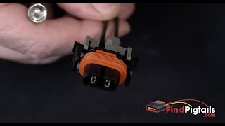
Typical fix: Reseat the loose pin(s) or repair the specific terminal. Clean any corrosion with electrical contact cleaner and apply dielectric grease before reconnecting. If the connector housing or terminals are damaged, it may need to be replaced with a new connector pigtail. 🎬 Learn how to properly depin and repair a wiring connector.
Est. part cost: $10-$150 - Chafed Wiring Harness 🟡 Medium Probability TSB #PIC4740E specifically calls out an inspection point for the ATS. The harness can rub against a securing bracket on the passenger side where the transmission bell housing meets the engine block. Another service update for some ATS models notes potential harness chafing near the generator drive belt pulley.
How to confirm: Visually inspect the wiring harness for signs of rubbing, abrasion, or exposed wires at the securing bracket mentioned in the TSB. The harness should hang below this bracket.
Typical fix: Repair the damaged wires using approved methods like soldering and heat shrink. Protect the harness from further chafing by re-routing it, adding protective conduit (anti-abrasion tape or a harness sleeve), and securing it with zip ties.
Est. part cost: $5-$50 - Faulty Body Control Module (BCM) or other Theft Deterrent Module ⚪ Low Probability → Shop Body Control Module
How to confirm: This is a diagnosis of exclusion. After all wiring, connector, and power/ground issues have been ruled out, a professional may use an advanced scan tool to test the module's communication and internal functions. The BCM is responsible for sending the fuel enable password, so if it's offline, P1629 will set.
Typical fix: Replace the faulty module. This requires programming the new module to the vehicle with specialized tools.
Est. part cost: $250-$600
Rare But Worth Checking
- Faulty Engine Control Module (ECM): → Shop Engine Control Module (ECM) The ECM is the module that sets the code, but it's rarely the cause of the failure. It should only be suspected after all wiring, connectors, and other modules have been thoroughly tested. On some platforms, the ECM is located in the wheel well, making its connectors vulnerable to moisture if a liner is damaged.
- Faulty Ignition Switch: → Shop Ignition Switch A failing ignition switch can cause intermittent power loss to various modules, leading to a communication breakdown and setting this code.
- Missing Power at ECM: A Reddit forum discussion on a 2014 ATS with a no-crank condition pointed to missing ignition hot wires at the ECM connector. This could be caused by a separate wiring fault or fuse issue upstream of the ECM.
Diagnosis Steps
- Check battery voltage to ensure it is stable 🎬 Watch: How a loose ground cable can cause no-start issues. and above 12.4V. Low voltage can cause communication errors.
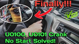
- Perform a full vehicle scan with a professional scan tool to capture all active and historical DTCs. Pay close attention to any U-prefix (communication) codes, especially U0100 and U0101.
- PRIORITY 1: Follow the diagnostic procedure from TSB #PIC4740E (or later revisions).
- Locate the transmission X1 connector. Disconnect it.
- Perform a wire 'tug test' by gently but firmly pulling on each individual wire at the back of the connector. A visual check is not enough, as a loose pin may look normal.
- Inspect the harness for chafing, especially at the securing bracket on the passenger side of the bell housing. Ensure the harness is routed correctly below the bracket.
- If a loose pin or chafed wire is found, repair it, clear the codes, and re-test.
- If no issues are found at the transmission harness, check for power at the ECM. A user on a forum fixed a similar no-crank issue by diagnosing missing power on specific pins. With the key on, backprobe ECM connector X1 at Pin 51 (Violet/Green) and Pin 73 (Violet/Blue) to check for voltage.
- If no wiring issues are found, proceed with advanced diagnostics to test the CAN bus network integrity (checking for 60 ohms of resistance across CAN lines at the DLC) and individual module communication.
Parts You'll Likely Need
- Transmission Wiring Harness Connector Pigtail
(OEM #Varies, visual confirmation required. Potential candidates include GM 88988938 or ACDelco PT3829.)— If the pins or the connector housing at the X1 location are corroded or damaged beyond repair, a new pigtail will be needed to be spliced into the harness.
Trusted brands: ACDelco, Dorman
OEM price range: $50-$100
Aftermarket price range: $25-$60
Related Codes That Often Appear With This One
- U0100 — Lost Communication With ECM/PCM. This indicates the root cause is a network failure preventing other modules from hearing the engine computer.
- U0101 — Lost Communication with TCM. 🎬 See this walkthrough for solving U0100 and U0101 communication codes. This is very common when the transmission X1 connector is the cause, as noted in TSB #PIC4740E. The TCM is a critical node on the network, and its loss triggers the security lockout.
- U0073 / U0074 — Control Module Communication Bus Off. These codes confirm a general network communication failure, strongly pointing to a wiring issue rather than a single component.
- P0700 — Transmission Control Module (TCM) Requested MIL Illumination. This code is set when the TCM detects a fault and asks the ECM to turn on the check engine light. It often accompanies the U-codes when the transmission connector is the issue.
Technical Service Bulletins (TSBs) & Recalls
- PIC4740E (and later revisions, e.g., PIC4740F): Addresses no-crank/no-start conditions, multiple warning lights, and communication DTCs (including P1629) caused by unseated pins in the transmission X1 connector or a chafed harness.
Platform-Specific Known Issues
- TSB #PIC4740E (and later revisions like PIC4740F) explicitly identifies a high probability of unseated pins in the transmission X1 connector causing a host of communication codes, including P1629.
- The same TSB also calls out a specific harness chafing point for the ATS model at a securing bracket near the transmission bell housing on the passenger side.
Mechanic-Grade Diagnostic Values
- High-Speed CAN Bus Network Resistance — expected: ~60 Ohms. Failure: A reading of ~120 Ohms indicates an open circuit to one of the two terminating resistors. A reading of 0 Ohms or very low resistance indicates a short between the CAN High and CAN Low wires.
- CAN High Voltage to Ground — expected: ~2.6V to 2.7V (average). Failure: Significant deviation from this voltage, or a reading of 0V or 5V, indicates a fault on the network. A reading of ~2.5V on both High and Low lines can indicate the wires are shorted together.
- CAN Low Voltage to Ground — expected: ~2.3V to 2.4V (average). Failure: Significant deviation from this voltage, or a reading of 0V, indicates a fault on the network.
Scan Tool Commands That Help
- GDS2 (GM Global Diagnostic System 2): Data Bus Diagnostic Tool — When multiple 'U' (communication) codes are present, this tool can be used to verify which specific control modules are active or inactive on the CAN bus, helping to isolate the point of failure.
- GDS2 / Tech 2 or Manual Procedure: Theft Deterrent Re-Learn / 30-Minute Manual Relearn — This is required after replacing the ECM or BCM to allow the modules to learn the vehicle's security password. The manual procedure can be done without a scan tool by turning the ignition ON for 10 minutes, OFF for 5 seconds, and repeating for a total of 3 cycles (30 minutes).
Wiring & Ground Locations
- G302 — Right kick panel area.. This is a primary ground point for the Body Control Module (BCM). A poor connection here can cause the BCM to malfunction or go offline, preventing it from sending the required security signal to the ECM.
- G104 (2013 4-Cyl) — Engine ground. Location moved from the front of the engine to the rear of the engine for automatic transmission models built after mid-December 2012.. This is a key engine ground. A poor connection can cause a wide range of issues, including no-start conditions and communication faults. The location change is a critical detail for 2013 models.
- Main Engine Ground (near fuse block) — Under the hood, next to the fuse block, connecting to the chassis.. A loose connection at this major ground point can cause high resistance during cranking, leading to a no-crank condition and extreme heat at the connection point. This can be misdiagnosed as a faulty starter or fuse box.
- CAN Bus Terminating Resistors — The High-Speed CAN bus has two 120-Ohm resistors. One is internal to the Engine Control Module (ECM). The other is at the opposite end of the bus, sometimes as an external plug-in resistor.. These resistors are essential for network stability. If the ECM or the wiring to the second resistor is compromised, the total network resistance will change from 60 Ohms to 120 Ohms, causing communication to fail and setting U-codes along with P1629.
Real Owner Repair Stories
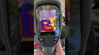
- YouTube channel 'Super Mario Diagnostics' (2014 Cadillac ATS) — Intermittent no-crank, no-start condition. Moving the underhood fuse box would sometimes allow it to start.
❌ Tried (didn't work) Replacing the underhood fuse box.
✅ What actually fixed it The main engine ground cable located next to the fuse box was loose. During a crank attempt, it would create high resistance and get extremely hot (measured over 360°F with a thermal camera), causing the no-start. Tightening the ground nut resolved the issue completely.
OEM Part Supersession History
12633555→12653998— Standard part revision and update by the manufacturer.
Heads up: The hardware family for 2013-2015 ATS models appears to be based on service number 12653998. Other numbers like 12659670 and 12656453 also exist for this application. Regardless of the part number used, the replacement ECM must be programmed to the vehicle's VIN and a theft deterrent relearn procedure must be performed.
Model Year Variations Within This Range
- 2013: For 4-cylinder (LCV, LTG) models with automatic transmissions, the engine ground G104 location was moved from the front of the engine to the rear of the engine starting in mid-December 2012. Technicians working on a 2013 model should verify the build date to know where to inspect this ground.
Helpful Videos

We Have This Part in Stock


The information in this article is provided for general reference and educational purposes only. Vehicle specifications, procedures, and part compatibility can vary by production date, trim level, and region. Always consult your vehicle's factory service manual and verify part numbers before purchasing or performing repairs. Safety-critical components such as airbags, seat belts, and braking systems should be installed by a qualified professional.
- Cadillac ATS:
- 🧭 Diagnostic Flowchart
- 🎬 Helpful Videos
- 🛍️ Shop This Part
- What's Unique About the 2013-2015 Cadillac ATS
- Symptoms You May Notice
- Most Likely Causes
- Rare But Worth Checking
- Diagnosis Steps
- Parts You'll Likely Need
- Related Codes That Often Appear With This One
- Technical Service Bulletins (TSBs) & Recalls
- Platform-Specific Known Issues
- Mechanic-Grade Diagnostic Values
- Scan Tool Commands That Help
- Wiring & Ground Locations
- Real Owner Repair Stories
- OEM Part Supersession History
- Model Year Variations Within This Range
- 🎟️ Get 5% Off