
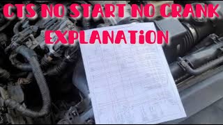
P1629 on 2004-2011 Cadillac CTS: Theft System No-Start Causes and Fixes
P1629 on a 2004-2011 Cadillac CTS means the anti-theft system has disabled the engine, causing a no-start. This is often due to a wiring or connector problem between modules, as noted in GM TSBs. The fix is usually repairing a corroded or loose wire, not replacing expensive modules.
- P1629 means your Cadillac's anti-theft system has disabled the engine, usually causing a no-start condition.
- Before replacing any expensive parts, thoroughly inspect vehicle wiring, especially the transmission X1 connector and ECM connectors, as per GM TSBs.
- This code is often accompanied by multiple 'U' (communication) codes, which strongly indicates a wiring or network problem rather than a single bad part.
- Due to the complexity of the anti-theft system and the need for programming new modules, professional diagnosis is highly recommended.
- Do not replace the starter or fuel pump; they are being disabled as a consequence of the P1629 fault, not as the cause.
What's Unique About the 2004-2011 Cadillac CTS

For this era of Cadillac CTS, which spans the first and second generations on the GM Sigma platform, the P1629 code is frequently linked to specific, documented wiring and communication issues rather than just a bad key. General Motors issued multiple Technical Service Bulletins (TSBs) pointing technicians toward known problem areas in the wiring harness, such as the transmission X1 connector or main power and data feeds to the ECM (specifically Class 2 data line CKT 1807). This is different from other vehicles where a similar code might more commonly point to a simple key transponder failure.
Diagnostic Flowchart

Tap your situation to follow the diagnostic path that matches what you're seeing on this vehicle.
Generation note: This range covers the end of the first generation (2004-2007) and the start of the second generation (2008-2011) CTS. The underlying cause related to communication errors between modules is common to both generations, as evidenced by TSBs that cover vehicles from both eras. A key difference is the communication protocol: 1st gen models use the single-wire Class 2 data bus 🎬 See how to diagnose and repair GM Class 2 data lines, while 2nd gen models (2008+) use the two-wire GMLAN (CAN bus) system.
Symptoms You May Notice
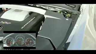
 🎬 Watch: Troubleshooting a 2008 CTS that won't crank or start warning message and illuminated security light." loading="lazy" style="max-width:100%;height:auto;border-radius:6px;display:block;box-shadow:0 2px 8px rgba(0,0,0,0.1);" />
- Engine will not crank or start.
- Engine starts briefly then immediately stalls.
- Key is stuck in the ignition lock cylinder.
- "Service Theft Deterrent System" message on the driver information center.
- Security light on the instrument panel is illuminated or flashing.
- Multiple other warning lights and messages due to network-wide communication loss.
- No power to dash, radio, or climate controls when the key is turned.
- Replacing the starter, as the symptom is often a 'no crank'. The starter is usually not the problem; it is not receiving the command to crank from the vehicle's modules.
- Replacing the fuel pump, because the engine won't run. The fuel pump is being intentionally disabled by the ECM due to the theft signal failure.
- Replacing the battery or alternator without proper diagnosis. While low system voltage can cause communication issues, a new battery won't fix a bad wire or failing module.
Most Likely Causes

- Wiring or Connector Fault 🔴 High Probability TSB #PIC4740E specifically calls out the transmission X1 connector as a potential point of failure causing communication loss. TSB #PIC5460B points to intermittent opens or shorts in the Ignition 1 Power Feed (CKT 5290) or the Class 2 data line (CKT 1807) to the ECM. These connectors and harnesses can be exposed to moisture, vibration, and chafing, leading to corrosion or backed-out pins.
How to confirm: Visually inspect the specified connectors (especially the transmission X1 connector and ECM connectors) for green corrosion, bent pins, or loose wires. Perform a 'wiggle test' on the harness while monitoring communication status with a scan tool. Use a multimeter to check for voltage on CKT 5290 and continuity on the data line (Class 2 or GMLAN) at the ECM connector.
Typical fix: Clean the connector terminals with a specialized contact cleaner, apply dielectric grease, and ensure it is fully seated. In some cases, the connector body, individual terminals, or a section of the wiring harness may need to be replaced.
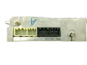
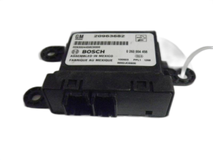
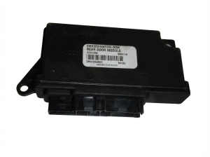
Est. part cost: $10-$75 - Faulty Body Control Module (BCM) 🟡 Medium Probability → Shop Body Control Module The BCM acts as a central gateway for various data networks and is responsible for reading the key and sending the 'ok to start' signal. Internal failures, such as cracked solder joints or damage from water intrusion, can cause intermittent communication issues, especially with temperature changes.
How to confirm: This requires an advanced scan tool to check for communication with the BCM and to see if it is recognizing the key correctly. If the module is not communicating or has internal fault codes, and its power and grounds are confirmed good, the module itself is suspect.
Typical fix: Replace the faulty module. The new module will require programming to the vehicle's VIN with a dealer-level scan tool or can be purchased pre-programmed.
Est. part cost: $250-$500 - Faulty Ignition Key or Ignition Lock Cylinder ⚪ Low Probability → Shop Ignition Switch The transponder chip in the key can fail, or the exciter ring in the ignition lock cylinder that reads the key can break. While possible, wiring issues are more frequently cited for this specific code on the CTS. A stuck key is often a symptom of the communication failure, not the cause.
How to confirm: Try starting the vehicle with a spare key. If the spare key works, the original key is faulty. If neither key works, the issue is more likely the lock cylinder, wiring, or a module. A stuck key often points back to a loss of power or communication to the lock solenoid, as described in TSB #PIC5460B.
Typical fix: Replace the faulty key and have it programmed to the vehicle. If the lock cylinder is bad, it will need to be replaced. A stuck key may be resolved by fixing the underlying electrical issue, such as a blown fuse or bad wire.
Est. part cost: $75-$300
Rare But Worth Checking
- Faulty Engine Control Module (ECM): → Shop Engine Control Module (ECM) While the ECM is the module setting the code, it's less likely to be the root cause than the modules or wiring sending it information. TSB #PIC5460B notes to suspect the ECM only after all wiring, connectors, and relays 🎬 Watch this explanation of how a bad ECM causes no-start have been thoroughly ruled out.
- Faulty Ignition Switch: → Shop Ignition Switch A failing ignition switch can cause a loss of power to multiple modules, leading to a communication breakdown and a P1629 code. Symptoms can overlap with a bad BCM, including a key that is stuck in the ignition. In some cases, a blown fuse related to the ignition switch circuit was the root cause.
Diagnosis Steps
- Connect a professional scan tool and check for codes in ALL modules (ECM, BCM, TCM, etc.). Pay close attention to any U-series communication codes, as they are a major clue.
- Check battery voltage and ensure it is stable and above 12.4 volts. Low voltage can cause random communication faults.
- Attempt to start the vehicle with a known-good spare key to rule out a faulty key transponder.
- Following TSB #PIC4740E, locate and inspect the transmission X1 connector for any signs of corrosion, moisture, or backed-out pins. Disconnect it and tug gently on each wire to check for unseated terminals.
- Following TSB #PIC5460B, check for battery voltage at the ECM fuse in the underhood fuse block. Then, check for voltage on the Ignition 1 power feed (CKT 5290) and check for an open/short on the Class 2 data line (CKT 1807) between the fuse block and the ECM.
- Using a scan tool, verify that the BCM (or TDM/RCDLR) is online and communicating. Check the data stream to see if it is recognizing the key state (e.g., On, Crank).
- For first-generation models, the ECM is located in the front driver's side wheel well, behind the fender liner, making it susceptible to moisture if the liner is damaged. Inspect the ECM and its connectors for corrosion.
- If all wiring, connectors, and power/grounds to the modules are confirmed good, the issue may be an internal failure of the BCM/TDM or, less commonly, the ECM.
Parts You'll Likely Need
- Wiring Connector Repair Kit — TSBs point to connector integrity as a primary cause. Often, cleaning the connector or replacing a single terminal is the fix, not replacing a whole component.
Trusted brands: ACDelco, Bosch (for connector components)
OEM price range: $20-$60
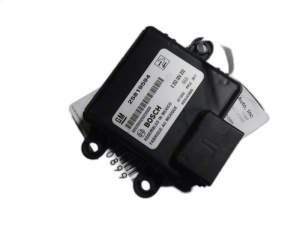
Aftermarket price range: $10-$40 - Body Control Module (BCM)
(OEM #25934762 (for 2008-2013 CTS, may be superseded by 84922494))— If wiring is confirmed good, the BCM is the next most likely cause as it is responsible for generating the anti-theft signal. It must be programmed after installation.
Trusted brands: ACDelco (GM Genuine)
OEM price range: $300-$500
Aftermarket price range: $200-$400
Related Codes That Often Appear With This One
- U0100 — Indicates 'Lost Communication With ECM/PCM'. This code is frequently seen with P1629 and points to a broader network communication problem, as cited in TSB #PIC4740E and #PIC5460B.
- U-codes (e.g., U0121, U0140, U2100, U1000) — These are all communication codes. Their presence alongside P1629 strongly suggests the root cause is a wiring harness or connector issue affecting the entire vehicle data bus, not just a single component failure. A forum post on ScannerDanner showed a 2006 CTS with P1629 accompanied by U1040, U1153, U1064, and U1192.
- P0700 — 'Transmission Control System Malfunction'. This can be triggered when communication is lost with the TCM, which can happen if the transmission X1 connector is faulty, as mentioned in TSB #PIC4740E.
Technical Service Bulletins (TSBs) & Recalls
- PIC4740E: Notes that P1629 can be stored with many other communication codes and advises inspection of the transmission X1 connector for unseated pins.
- PIC5460B: Connects P1629 to no-crank/key-stuck conditions and other Class 2 communication codes, suggesting a fault in the Ignition 1 power feed (CKT 5290) or Class 2 data line (CKT 1807) to the ECM.
Platform-Specific Known Issues
- TSB #PIC4740E highlights that various communication DTCs, including P1629, can be caused by a poor connection at the transmission X1 connector. The fix involves checking for unseated pins by tugging on each wire.
- TSB #PIC5460B links P1629 with a no-crank or key-stuck-in-ignition concern, pointing towards potential issues in the ECM's Ignition 1 Power Feed (CKT 5290) or the Class 2 data line (CKT 1807).
- On first-generation CTS models, the ECM is located behind the driver-side front wheel liner, a location that can be vulnerable to water intrusion and corrosion if the liner is damaged or missing.
Mechanic-Grade Diagnostic Values
- Class 2 Serial Data Line Voltage (2004-2007) — expected: Toggles between 0V (inactive) and 7V (active). A scope should show square wave data packets moving normally with a peak around 6-7V.. Failure: Voltage stuck high, stuck low, or showing no activity indicates a short, open, or module failure on the bus.
- High-Speed GMLAN Bus Resistance (2008-2011) — expected: Approximately 60 Ohms when measured between Pin 6 (GMLAN-H) and Pin 14 (GMLAN-L) at the DLC with the battery disconnected.. Failure: A reading of 120 Ohms indicates one of the two terminating resistors is open. A reading of 0 Ohms indicates the high and low circuits are shorted together.
- High-Speed GMLAN Bus Voltage (2008-2011) — expected: At rest (recessive state), both GMLAN-High (Pin 6) and GMLAN-Low (Pin 14) should be at 2.5V. During communication (dominant state), GMLAN-High goes to ~3.5V and GMLAN-Low goes to ~1.5V.. Failure: Voltages that are stuck, do not toggle, or are outside these ranges point to a wiring fault or a module pulling the bus down.
Scan Tool Commands That Help
- GM Tech 2 / GDS2: BCM Special Functions > New BCM Setup — This function is required after installing a new Body Control Module to program the vehicle's RPO codes and VIN, allowing it to communicate with other modules.
- GM Tech 2 / GDS2: Theft Deterrent > Programming Theft Deterrent System Components — Used to initiate the password learning process between the BCM/RCDLR and the ECM after one of those components has been replaced.
- Manual Procedure (No Scan Tool): 30-Minute Security Relearn Procedure — Can be used after replacing a key or module if a dealer-level scan tool is not available. It involves cycling the ignition key to 'ON' for three consecutive 10-minute intervals to allow the modules to relearn the key's transponder or the new module's password.
Wiring & Ground Locations
- G102 / G103 / G106 / G131 — For 2008+ models: G102 is on the right front of the engine compartment. G106 and G131 are on the rear of the engine block. For earlier models, G102/G107 are on the engine block near the ignition coils. These grounds are critical for the ECM.. The ECM and BCM rely on clean, tight ground connections. A poor engine or chassis ground can cause a voltage drop or electrical noise, disrupting the sensitive communication signals between modules and triggering P1629 and other U-codes.
- G201 / G200 — Located in the right (G201) and left (G200) kick panel areas.. These are the primary interior grounds for the Body Control Module (BCM) and other dash components. A loose or corroded ground here directly impacts the BCM's ability to function and communicate with the ECM.
- ECM Connector C1, Pin 15/16 (2004-2007) — At the Engine Control Module, which is often located behind the driver's side front wheel well liner.. These pins carry the Class 2 Serial Data signal (Purple wire, CKT 1807). This is the specific wire that carries the theft deterrent password from the BCM to the ECM. Probing here can confirm if the signal is present.
- ECM Connector, Pin 19 (2004-2007) — At the Engine Control Module connector.. This is the Ignition 1 Voltage feed (Pink wire, CKT 239/5290). Loss of this signal due to a wiring fault is a cause cited in TSB #PIC5460B.
Real Owner Repair Stories
- Reddit user in r/AutoMechanics (Cadillac CTS (year not specified, but symptoms match)) — No crank, no start, key gets stuck in ignition, security light on, code U0100 (Lost Communication with ECM).
❌ Tried (didn't work) Replaced camshaft components, confirmed engine timing and compression were good, cleared codes (they returned immediately).
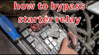
✅ What actually fixed it A temporary workaround was discovered: by manually jumping the starter relay once, the modules would 'wake up' and communicate, allowing the car to start normally with the key for about an hour. After sitting longer, the fault would return. This strongly points to a module communication handshake failure upon initial key-on, rather than a hard part failure. The final fix was not posted, but the diagnosis isolates the problem to the initial communication sequence. - ScannerDanner Forum user (2006 Cadillac CTS 2.8L) — No Crank, No start. Codes P1629, U1040, U1153, U1064, U1192, P0318, and U1000 in other modules.
❌ Tried (didn't work) User was in the process of diagnosis, confirming the Class 2 data line waveform looked good on an oscilloscope.
✅ What actually fixed it The thread did not have a final confirmed fix, but the collection of codes strongly supported the TSBs pointing to a network-wide communication fault originating from a wiring or connector issue, rather than a single failed module. The user was correctly focused on network diagnostics rather than individual component replacement.
OEM Part Supersession History
25934762→84922494 (unconfirmed, but a common replacement path)— Part revision and consolidation by GM.
Heads up: When replacing the BCM, even with a pre-programmed unit, a 'Setup SDM Primary Key in BCM' procedure may be required with a professional scan tool if the airbag (SIR) warning light comes on after installation.
Model Year Variations Within This Range
- 2004-2007: These first-generation models use the GM Class 2 serial data bus for module communication. This is a single-wire (typically purple) network that toggles between 0 and 7 volts. Diagnosis focuses on this single circuit (CKT 1807).
- 2008-2011: These second-generation models use the faster, more robust two-wire High-Speed GMLAN (CAN bus). This network uses a twisted pair of wires (GMLAN-H and GMLAN-L) and is diagnosed by checking for 60-ohm resistance between them. The BCM acts as the central gateway module for the various bus systems.
Helpful Videos

We Have This Part in Stock

The information in this article is provided for general reference and educational purposes only. Vehicle specifications, procedures, and part compatibility can vary by production date, trim level, and region. Always consult your vehicle's factory service manual and verify part numbers before purchasing or performing repairs. Safety-critical components such as airbags, seat belts, and braking systems should be installed by a qualified professional.
- Cadillac CTS:
- 🧭 Diagnostic Flowchart
- 🎬 Helpful Videos
- 🛍️ Shop This Part
- What's Unique About the 2004-2011 Cadillac CTS
- Symptoms You May Notice
- Most Likely Causes
- Rare But Worth Checking
- Diagnosis Steps
- Parts You'll Likely Need
- Related Codes That Often Appear With This One
- Technical Service Bulletins (TSBs) & Recalls
- Platform-Specific Known Issues
- Mechanic-Grade Diagnostic Values
- Scan Tool Commands That Help
- Wiring & Ground Locations
- Real Owner Repair Stories
- OEM Part Supersession History
- Model Year Variations Within This Range
- 🎟️ Get 5% Off