
P1629 on 2004-2008 Cadillac SRX: Theft System, No-Start Causes and Fixes
P1629 on a 2004-2008 Cadillac SRX means the anti-theft system has disabled the engine, causing a no-start or key-stuck-in-ignition issue. This is almost always caused by a communication failure due to faulty wiring or connectors, not a bad module. Check the transmission's main electrical connector (X1) for loose pins and the ECM power/data wiring (Circuits 5290 & 1807) before replacing any parts, as specified in GM TSBs.
- P1629 means your SRX's anti-theft system has disabled the engine due to a communication error.
- Do not assume a major component has failed. The most likely cause is a wiring or connector issue.
- Always check for other codes, especially 'U' codes, as they will help pinpoint the location of the communication failure.
- The two most probable causes, backed by TSBs, are a bad connection at the transmission's main electrical plug or a wiring issue near the ECM.
- This is a complex electrical issue; professional diagnosis is strongly recommended to avoid replacing expensive parts unnecessarily.
What's Unique About the 2004-2008 Cadillac SRX
For the first-generation Cadillac SRX and its platform mates (CTS, STS), this code is frequently linked to specific, documented wiring and connector vulnerabilities. General Motors has issued Technical Service Bulletins (TSBs) that point directly to communication breakdowns at the main transmission connector (X1) and in the power feed and data wiring to the ECM as the root cause. Unlike many other vehicles where this code might point to a bad key or ignition switch, on the SRX, the problem is more often in the complex data network wiring that is susceptible to corrosion and intermittent connections.
Diagnostic Flowchart
Tap your situation to follow the diagnostic path that matches what you're seeing on this vehicle.
Symptoms You May Notice
- Engine fails to crank or will not start.
- Key is stuck in the ignition lock cylinder.
- "Service Theft Deterrent System" message on the driver information center.
- Security indicator light is illuminated or flashing on the instrument panel.
- Multiple other warning lights and messages due to network-wide communication loss.
- Power windows, radio, or other interior accessories may not function correctly.
- Replacing the battery without diagnosing the underlying electrical fault.
- Replacing the key fob or transponder key, as the issue is a communication failure, not a key recognition problem.
- Replacing the fuel pump, because the no-start is caused by the ECM actively disabling the fuel system, not a failed pump.
- Replacing the ECM without first exhaustively testing the wiring and connectors as outlined in TSBs.
Most Likely Causes
- Communication Loss at Transmission X1 Connector 🔴 High Probability → Shop Transmission Assembly As cited in GM TSB #PIC4740E, the main transmission harness connector (X1) is a known failure point. Its location makes it vulnerable to moisture and vibration, leading to corrosion or unseated terminal pins that disrupt communication between the ECM, TCM, and other modules.
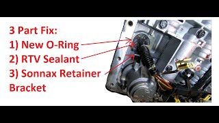
How to confirm: Visually inspect the large, lever-lock style connector on the driver 🎬 See how to fix leaks and issues at the transmission connector's side of the transmission. Look for any signs of green or white corrosion or moisture. Crucially, disconnect the connector and gently tug on each individual wire. A pin can appear seated but fail to make contact under load; the TSB notes that a side load can cause a false positive lock.
Typical fix: Clean the connector terminals with a specialized contact cleaner and a small brush. Reseat any loose terminals until they click. If terminals are heavily corroded or damaged, the connector pigtail or individual terminals may need to be replaced. Apply dielectric grease during reassembly to prevent future moisture intrusion.
Est. part cost: $10-$50 - Intermittent Power or Ground to the ECM 🟡 Medium Probability GM TSB #PIC5460B specifically calls out intermittent connections in the Ignition 1 power feed (circuit 5290) or the Class 2 data line (circuit 1807) to the ECM as a cause for P1629, often accompanied by a no-crank and key-stuck-in-ignition condition. This can be due to a faulty powertrain relay, a break in the wiring, or a poor connection at the fuse block.
How to confirm: Using a multimeter, verify battery voltage at the ECM fuse in the underhood fuse block. Then, probe the ECM connector to check for consistent voltage at the Ignition 1 power feed wire (CKT 5290). Test the Class 2 data line (CKT 1807) for an open or short circuit between the Data Link Connector (DLC) and the ECM.
Typical fix: Repair the open or short in the affected wire. This often involves tracing the harness and repairing a chafed or broken section. If the powertrain relay is faulty, it will need to be replaced.
Est. part cost: $5-$30 - Faulty Ignition Lock Cylinder or Switch ⚪ Low Probability → Shop Ignition Switch While less common than wiring issues on this platform, a failing ignition switch can cause a communication breakdown and trigger a P1629 code, sometimes causing the key to get stuck. However, the stuck key is often a symptom of the power/data loss described in TSB #PIC5460B, not the cause itself.
How to confirm: A scan tool can be used to monitor the status of the ignition switch. A technician can also test the electrical outputs from the switch to see if they are within specification. If the key is stuck due to a dead battery or electrical fault, there is often a manual release tab under the steering column.
Typical fix: Replacement of the ignition lock cylinder and/or the electrical portion of the ignition switch. This may require a security relearn procedure.
Est. part cost: $100-$250
Rare But Worth Checking
- Faulty Engine Control Module (ECM): → Shop Engine Control Module (ECM) The ECM is the module that sets the code because it isn't receiving the correct signal. It is rarely the source of the problem itself. TSB #PIC5460B advises only suspecting the ECM after all wiring, connectors, and relays have been confirmed to be in good working order.
- Faulty Body Control Module (BCM): → Shop Body Control Module The BCM is often the module responsible for sending the theft deterrent password. A failure in the BCM or its wiring can cause this code. A scan tool that can check for communication with the BCM is essential for diagnosis.
Diagnosis Steps
- Connect a professional, bi-directional scan tool and perform an 'auto scan' to check for all stored DTCs in all modules (ECM, BCM, TCM, ABS, etc.). Pay close attention to any 'U' (network) codes, as they are key to diagnosing P1629.
- Note which modules are not communicating. If the ECM is not responding, this confirms the direction of the problem.
- Inspect the vehicle battery and charging system to ensure stable voltage above 12.4V is present. Low voltage can cause widespread communication faults.
- Following TSB #PIC4740E, locate and thoroughly inspect the transmission X1 connector. Disconnect, clean, and perform a 'tug test' on each wire to ensure terminals are fully seated.
- Following TSB #PIC5460B, check for battery voltage at the ECM fuse in the underhood fuse block. Then, check for battery voltage at the ECM connector's Ignition 1 power feed wire (CKT 5290).
- Test the Class 2 data line (CKT 1807) for continuity, shorts to power, or shorts to ground between the ECM and the Data Link Connector (Pin 2).
- Inspect the main powertrain relay and its connections in the underhood fuse block.
- If the key is stuck, check for a manual interlock bypass release, which is often a small plug under the steering column 🎬 Watch: How to release a stuck key in your SRX that allows a tool to be inserted to release the key.
- Only consider the ECM or BCM as the potential failure after all wiring, connectors, and relays have been confirmed to be in good working order.
Parts You'll Likely Need
- Transmission Connector Pigtail/Terminals
(OEM #Varies (e.g., ACDelco PT series). Must be verified by VIN.)— This is the most common failure point identified in TSB #PIC4740E. Corrosion often damages the terminals or the connector housing itself, requiring replacement of the pigtail or individual terminal pins.
Trusted brands: ACDelco, Dorman
OEM price range: $40-$80
Aftermarket price range: $20-$50 - Ignition Lock Cylinder — A mechanical or electrical failure in the lock cylinder can cause the key to get stuck and disrupt communication with the theft deterrent system, as noted in TSB #PIC5460B. However, this is less common than wiring faults.
Trusted brands: ACDelco, Standard Motor Products
OEM price range: $150-$250
Aftermarket price range: $80-$150
Related Codes That Often Appear With This One
- U0100 — Indicates a general loss of communication with the ECM. P1629 is a specific result of this communication loss, and this code is frequently stored in other modules when P1629 is present in the ECM.
- U2100 — Indicates a CAN bus communication malfunction, often pointing to the network wiring issues described in TSB #PIC4740E.
- U0121 — Indicates loss of communication with the Anti-lock Brake System (ABS) module, further suggesting a widespread network issue originating from a shared connector like the transmission X1.
- P0700 — This is a request from the Transmission Control Module (TCM) to illuminate the check engine light. It often appears with P1629 when the transmission X1 connector is the source of the communication fault.
Technical Service Bulletins (TSBs) & Recalls
- PIC4740E: Loss of communication with TCM/ECM, points to inspecting the transmission X1 connector.
- PIC5460B: No crank or key stuck in ignition, points to checking power feed (CKT 5290) and Class 2 data wiring (CKT 1807) to the ECM.
Platform-Specific Known Issues
- TSB #PIC4740E: Notes that a loss of communication between the TCM and ECM, triggering P1629 and numerous other 'U' codes, can be caused by unseated pins in the transmission X1 connector. The bulletin specifically advises tugging on each wire to confirm it is locked in place.
Mechanic-Grade Diagnostic Values
- Class 2 Serial Data Line Voltage (CKT 1807) — expected: Fluctuating voltage between 0V and 7.0V with the key on.. Failure: A steady 0V indicates a short to ground. A steady voltage (e.g., 5V or 12V) indicates a short to power. No voltage could be an open circuit.
- Ignition 1 Voltage at ECM (CKT 5290) — expected: Battery voltage (approx. 12.6V with key on, engine off).. Failure: Voltage significantly less than battery voltage indicates high resistance, an open circuit, or a faulty relay.
- ECM Ground Connection Resistance — expected: Less than 5 ohms between the ECM ground pin at the connector and the negative battery terminal.. Failure: High resistance indicates a corroded or loose ground connection, which can cause intermittent module operation.
Scan Tool Commands That Help
- GM Tech2 / GDS2: Ping Modules — Used to actively check which modules on the Class 2 network are responding. If the ECM or BCM/TDM does not respond to the ping, it helps isolate the source of the communication loss.
- GM Tech2 / GDS2: Output Tests > Dash Integration Module (DIM) > Park Key Lock Relay — If the key is stuck in the ignition, this command can be used to manually activate the release solenoid. If the solenoid activates but the key remains stuck, it points to a mechanical issue in the lock cylinder. If it doesn't activate, it confirms an electrical control problem.
- GM Tech2 / GDS2: Theft Deterrent > Re-Learn Pass-Key — This function is required after replacing the ECM or BCM/Theft Deterrent Module to make the modules learn the new security password.
- None (Manual Procedure): 30-Minute Security Relearn Procedure — Can be attempted after part replacement if a scan tool is unavailable. It involves cycling the key to 'ON' for three consecutive 10-minute intervals. The security light should change state after each 10-minute cycle. This allows modules to relearn the key's password.
Wiring & Ground Locations
- CKT 1807 (Class 2 Data) — Purple wire at Pin 48 of the C2 (Blue) ECM connector. Also found at Pin 2 of the Data Link Connector (DLC).. This is the specific wire that carries the theft deterrent 'password' signal to the ECM. An open or short on this wire is a direct cause of P1629, as cited in TSB #PIC5460B.
- CKT 5290 (Ignition 1 Power) — Pink wire at the ECM connector. It originates from the underhood fuse block (ECM fuse) and is controlled by the powertrain relay.. This circuit provides the main key-on power to the ECM. An intermittent open on this wire will cause the ECM to lose power, preventing it from receiving the theft signal and leading to a no-start and P1629.
- G102 (ECM Ground) — Located on the right side of the engine for 2004 models, and on the right rear of the engine for 2006 models.. This is a primary ground point for the Engine Control Module. A loose or corroded connection here can cause intermittent ECM operation and communication faults like P1629.
- X1 Transmission Connector — A large, 16-way, lever-lock style connector located on the driver's side of the transmission housing.. This connector is a major communication hub, with Class 2 data lines passing through it. As noted in TSB #PIC4740E, corrosion or unseated pins in this connector are a very common cause of network-wide communication loss, triggering P1629.
Real Owner Repair Stories
- YouTube user comment (2004-2009 Cadillac SRX (model year not specified)) — Intermittent no-start, would sometimes start after wiggling connectors in the underhood fuse box. Car would stall while driving. "No Remote Detected" message even with remote present.
❌ Tried (didn't work) Wiggling ECM/TCM connectors., Checking battery connections.
✅ What actually fixed it The 250-amp main fuse on the positive battery cable terminal/fuse block assembly was making a bad connection and coming apart. Replacing the entire positive battery cable and fuse block assembly (sold as one unit from GM) resolved the intermittent power loss and no-start condition.
Model Year Variations Within This Range
- 2004 vs 2006: The physical location of the main ECM ground point G102 changes. On 2004 models, it is on the right side of the engine. On 2006 models, it is on the right rear of the engine.
Helpful Videos
We Have This Part in Stock


The information in this article is provided for general reference and educational purposes only. Vehicle specifications, procedures, and part compatibility can vary by production date, trim level, and region. Always consult your vehicle's factory service manual and verify part numbers before purchasing or performing repairs. Safety-critical components such as airbags, seat belts, and braking systems should be installed by a qualified professional.
- Cadillac SRX:
- 🧭 Diagnostic Flowchart
- 🎬 Helpful Videos
- 🛍️ Shop This Part
- What's Unique About the 2004-2008 Cadillac SRX
- Symptoms You May Notice
- Most Likely Causes
- Rare But Worth Checking
- Diagnosis Steps
- Parts You'll Likely Need
- Related Codes That Often Appear With This One
- Technical Service Bulletins (TSBs) & Recalls
- Platform-Specific Known Issues
- Mechanic-Grade Diagnostic Values
- Scan Tool Commands That Help
- Wiring & Ground Locations
- Real Owner Repair Stories
- Model Year Variations Within This Range
- 🎟️ Get 5% Off