
P2544 on 2013-2015 Cadillac ATS: Torque Management Signal Fault Causes and Fixes
On a 2013-2015 Cadillac ATS, code P2544 is almost always caused by a poor electrical connection at the main transmission wiring harness connector (X1). This causes harsh, banging shifts. The fix is typically inspecting and repairing the connector pins, as documented in GM TSB #PIC4740F, which is a labor-intensive but low parts-cost repair.
- P2544 on a 2013-2015 ATS is a communication code, not an internal transmission failure, despite the violent shifting symptoms.
- The most likely cause is a poor connection at the main transmission wiring harness (X1 connector) or a chafed wire, as documented in GM TSB PIC4740F.
- Diagnosis requires a physical 'tug test' of each wire in the X1 connector, as a simple visual check is not sufficient.
- Before replacing any expensive modules, the wiring and connector inspection outlined in the TSB must be performed.
What's Unique About the 2013-2015 Cadillac ATS
For the 2013-2015 Cadillac ATS, this code is very specifically linked to a known issue documented in GM Technical Service Bulletin PIC4740F. The bulletin highlights a high probability of unseated pins in the transmission's main X1 wiring connector or a chafed harness near the bell housing. Technicians are explicitly warned that a visual check of the connector is not enough; a physical 'tug test' on each individual wire is required because the pins can have a 'false positive lock' where they feel seated but are not making a secure connection. The TSB also notes a specific chafing point for the ATS harness at the securing bracket on the passenger side where the transmission bell housing attaches to the engine block.
Diagnostic Flowchart
Tap your situation to follow the diagnostic path that matches what you're seeing on this vehicle.
Symptoms You May Notice
- Extremely harsh, banging, or slamming gear shifts
- Check Engine Light (MIL) illuminated
- Service StabiliTrak or Traction Control warning lights
- Vehicle enters 'Reduced Engine Power' mode
- No-crank or no-start condition
- Door locks cycling intermittently while driving
- Failure of paddle shifters and loss of rev-matching after applying an aftermarket engine tune
- Replacing the Transmission Control Module (TCM) before thoroughly inspecting the X1 connector and wiring harness per TSB PIC4740F.
- Performing a transmission fluid flush or service, assuming the harsh shifting is an internal hydraulic or mechanical issue.
- Replacing the entire transmission, which is an extremely expensive and unnecessary repair for this communication fault.
Most Likely Causes
- Unseated pins or poor connection at the transmission X1 connector 🔴 High Probability → Shop Transmission Assembly This is a documented weak point for this platform, as specified in GM Technical Service Bulletin #PIC4740F. The bulletin notes that pins can feel locked in place when they are not, leading to intermittent communication loss due to vibration or thermal expansion.
How to confirm: Disconnect the transmission X1 connector. Per the TSB, you must carefully tug on each individual wire to ensure it is fully seated and locked. A visual inspection is not sufficient, as a 'false positive lock' can occur. Inspect the male and female terminals for signs of corrosion (green or white powder), moisture, or spread/widened pins.
Typical fix: Reseat any loose pins. Use electronic contact cleaner to clean both sides of the connector. If terminals are corroded or spread, they may need to be replaced individually 🎬 See this guide on how to depin the wiring harness or as a complete connector pigtail. Apply dielectric grease to the connector seal before reassembly to prevent future moisture intrusion.
Est. part cost: $0-$70 - Chafed or damaged wiring harness 🟡 Medium Probability TSB #PIC4740F specifically calls out an inspection point for the Cadillac ATS: the harness securing bracket on the passenger side where the transmission bell housing attaches to the engine block. The harness can rub against this bracket, causing a short to ground or a break in the wire.
How to confirm: Visually inspect the wiring harness in the area specified by the TSB for signs of rubbing, exposed copper wires, or damage to the loom. The harness should hang below the bracket, not be pinched by it.
Typical fix: Repair the damaged section of wire using solder and heat-shrink tubing. Re-route or add protective conduit to the harness to prevent future chafing against the bracket.
Est. part cost: $0-$25
Rare But Worth Checking
- Faulty Transmission Control Module (TCM): → Shop Transmission Assembly This should only be considered after all wiring and connector issues have been definitively ruled out. Module failure is far less common than the documented wiring problems.
- Faulty Engine Control Module (ECM): → Shop Engine Control Module (ECM) This is an extremely rare cause for this specific code. The ECM is typically the module reporting the fault, not the source of it.
- Aftermarket Engine/Transmission Tune: → Shop Transmission Assembly In some cases, applying an aftermarket performance tune can trigger a P2544 code if the tune's torque management parameters are not compatible with the vehicle's software, as reported by owners. The code may not appear on the stock tune.
Diagnosis Steps
- Perform a full vehicle scan with a professional scan tool to record P2544 and all other stored DTCs, especially any U-codes (communication) or C-codes (chassis).
- Obtain and review Technical Service Bulletin #PIC4740F for specific instructions related to this vehicle.
- Disconnect the negative battery terminal.
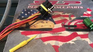
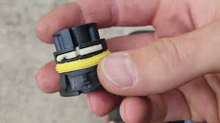
- Locate and disconnect the main transmission wiring harness connector (X1). It is a large, round connector on the side of the transmission. 🎬 Watch: A helpful tutorial on the 6L80e connector and pins
- Perform a 'tug test' on each individual wire going into the connector to ensure every pin is fully seated and locked. Do not rely on a visual check alone.
- Inspect the connector terminals (both male and female sides) for corrosion, moisture, or damaged/spread pins.
- Inspect the wiring harness for chafing or damage, paying close attention to the area near the securing bracket on the passenger side of the bell housing.
- If a wiring or pin issue is found, repair it. Clean terminals with contact cleaner, reseat pins, and apply dielectric grease before reconnecting.
- Reconnect the battery, clear all codes, and perform a test drive to see if the code returns.
- If no wiring issues are found, further diagnostics on the CAN bus network resistance (should be ~60 Ohms) 🎬 Watch: How to diagnose voltage loss on GM 6-speed transmissions and module power/grounds would be required before condemning a control module.
Parts You'll Likely Need
- Transmission Wire Harness Connector Pigtail
(OEM #ACDelco PT2713 (GM 13584095))— Needed if the original connector housing or terminals are damaged by corrosion, heat, or physical damage and cannot be salvaged. This part allows splicing in a new connector.
Trusted brands: ACDelco, Dorman
OEM price range: $30-$60
Aftermarket price range: $20-$50 (e.g., Dorman 645-500) - Dielectric Grease — Recommended to apply to the connector seal upon reassembly to prevent moisture intrusion and corrosion.
Trusted brands: Permatex, CRC
OEM price range: $5-$15
Aftermarket price range: $5-$15
Related Codes That Often Appear With This One
- P0700 — P0700 is a generic code that means the TCM has stored a fault. It's a flag telling the technician to check the transmission system for specific codes like P2544.
- U0073, U0100, U0101, U0121, U0140 — These are network communication (CAN bus) fault codes. Their presence strongly reinforces the diagnosis of a wiring or connector issue, as a physical fault at the X1 connector will disrupt communication for multiple modules simultaneously. All are listed in TSB PIC4740F.
- C0561 — This code relates to the StabiliTrak system. The traction control system relies on torque management signals, so when communication is lost, it will also set a fault.
Technical Service Bulletins (TSBs) & Recalls
- PIC4740F: Supersedes PIC4740E. Addresses multiple communication DTCs (P2544, U0100, etc.), no-crank, and harsh shifting caused by unseated pins in the transmission X1 connector or a chafed harness. Provides specific inspection details for the ATS.
Platform-Specific Known Issues
- TSB #PIC4740F documents a known issue with unseated terminals in the transmission X1 connector causing a wide range of communication DTCs, including P2544.
- The same TSB also identifies a potential harness chafing point for the ATS at the securing bracket on the passenger side of the transmission bell housing.
Mechanic-Grade Diagnostic Values
- CAN Bus Network Resistance — expected: ~60 Ω (Ohms) with battery disconnected. Failure: A reading of ~120 Ω indicates an open circuit in the network or one of the terminating modules. A reading significantly less than 60 Ω indicates a short between the CAN High and CAN Low wires.
- GMLAN CAN High Voltage — expected: Fluctuates between 2.5V and 3.5V (Key On, Engine Off). Failure: Voltage that is stuck high, low, or at 0V indicates a circuit fault.
- GMLAN CAN Low Voltage — expected: Fluctuates between 2.5V and 1.5V (Key On, Engine Off). Failure: Voltage that is stuck high, low, or at 0V indicates a circuit fault.
- System Voltage — expected: >12.4V (engine off), 13.7V - 14.7V (engine on). Failure: Low voltage can cause unpredictable communication errors across various modules.
Scan Tool Commands That Help
- GDS2 / Professional Scan Tool: Module Self-Test — After verifying wiring integrity, a self-test can be commanded for the ECM/PCM. If the module reports an internal failure of its torque-request input channel, the fault is likely internal to the module itself, though this is rare.
- GDS2 / Professional Scan Tool: CAN Bus Error Frame Scan — To check for general network instability. A high error count on the bus ID used by the TCM can indicate a communication problem, reinforcing the diagnosis of a wiring or connector issue.
Wiring & Ground Locations
- X1 Connector — The main round electrical harness connector on the side of the transmission.. This is the primary failure point documented in TSB PIC4740F. Unseated pins or corrosion here directly severs communication between the TCM and ECM, causing P2544 and a host of other U-codes.
- G104 — Main engine ground. For 3.6L V6 models, it's on the front of the right cylinder head. For 2.0T/2.5L 4-cylinder models, the location changed mid-2013: on vehicles built before mid-Dec 2012, it's at the front of the engine; on later models, it's at the lower rear of the cylinder head.. A poor engine ground can cause unstable voltage and electrical noise, disrupting communication between modules mounted on the engine/transmission and the rest of the vehicle.
- G201 — Located in the driver's side kick panel area.. This is a major interior ground point. While less likely to be the cause than engine-side grounds, a fault here could affect modules inside the cabin that communicate on the same network.
- OBD-II DLC Pins 6 & 14 — The Data Link Connector under the driver's side dashboard.. These are the termination points for the High-Speed GMLAN (CAN Bus) network. Technicians use these pins to measure the overall health of the network by checking for the ~60 Ohm resistance.
OEM Part Supersession History
13504128, 19115594, 88988106→GM 13584095 (ACDelco PT2713)— Part consolidation and revision over time.
Model Year Variations Within This Range
- 2013: The location of the main engine ground (G104) on 4-cylinder (LCV, LTG) automatic transmission models changed. For vehicles produced before mid-December 2012, the ground is at the front of the engine. For vehicles produced after that date, it is located at the rear of the engine.
Helpful Videos

We Have This Part in Stock


The information in this article is provided for general reference and educational purposes only. Vehicle specifications, procedures, and part compatibility can vary by production date, trim level, and region. Always consult your vehicle's factory service manual and verify part numbers before purchasing or performing repairs. Safety-critical components such as airbags, seat belts, and braking systems should be installed by a qualified professional.
- Cadillac ATS:
- 🧭 Diagnostic Flowchart
- 🎬 Helpful Videos
- 🛍️ Shop This Part
- What's Unique About the 2013-2015 Cadillac ATS
- Symptoms You May Notice
- Most Likely Causes
- Rare But Worth Checking
- Diagnosis Steps
- Parts You'll Likely Need
- Related Codes That Often Appear With This One
- Technical Service Bulletins (TSBs) & Recalls
- Platform-Specific Known Issues
- Mechanic-Grade Diagnostic Values
- Scan Tool Commands That Help
- Wiring & Ground Locations
- OEM Part Supersession History
- Model Year Variations Within This Range
- 🎟️ Get 5% Off