
P2797 on 2009-2013 Cadillac Escalade EXT: Aux Pump Circuit Fault Causes & Fixes
On a 2009-2013 Escalade Hybrid, code P2797 almost always points to a wiring issue between the Hybrid Powertrain Control Module (HPCM) and the auxiliary transmission pump, not a failed pump. A GM Technical Service Bulletin (PIP4873A) specifically advises inspecting the wiring harness for damage, chafing, or backed-out connector pins before replacing any parts. The code often appears with P0C2B and P0AC4 and causes a noticeable jerk or hesitation when the vehicle switches between gas and electric
- Do not immediately assume the auxiliary transmission pump has failed. The problem is most likely in the wiring.
- Reference GM Technical Service Bulletin PIP4873A before starting any diagnosis or repair.
- Thoroughly inspect the wiring harness and connectors between the hybrid computer (HPCM) and the pump control module for any signs of damage, chafing, or corrosion.
- This code indicates a serious issue that can affect drivability and potentially harm the transmission; it should be addressed promptly.
- Due to the complexity and high-voltage components of the hybrid system, professional service is strongly recommended.
What's Unique About the 2009-2013 Cadillac ESCALADE EXT
The 2009-2013 Cadillac Escalade EXT uses a sophisticated GM 2-Mode Hybrid system (RPO HP2). This system relies on an auxiliary electric transmission pump to function during its engine-off 'Auto-Stop' mode. While many vehicles now have similar pumps for start-stop systems, this specific platform is subject to a well-documented issue where the wiring harness is the most common point of failure, a fact highlighted in a specific Technical Service Bulletin (TSB PIP4873A) that warns technicians against immediately replacing the pump. The control module for the pump is located in the engine compartment, near the A/C compressor and power inverter module.
Diagnostic Flowchart
Tap your situation to follow the diagnostic path that matches what you're seeing on this vehicle.
Symptoms You May Notice
- Harsh shifting, especially when coming to a stop or accelerating from a stop
- Vehicle surges or lunges during deceleration or when switching between hybrid and engine modes (often called the 'bump/jerk').
- Vehicle fails to move after an "Auto-Stop" event
- Check Engine Light or Malfunction Indicator Lamp (MIL) is illuminated.
- "Service Hybrid System" message on the instrument cluster.
- Auto-Stop feature becomes inoperative.
- "Emissions System Not Ready" message may appear.
- Replacing the auxiliary transmission fluid pump without first thoroughly inspecting the wiring harness and connectors as per TSB PIP4873A.
Most Likely Causes
- Damaged Wiring or Poor Connection 🔴 High Probability Multiple GM Technical Service Bulletins (PIP4873A, PIT4853D, 19-NA-200) identify this as the most likely cause. Harnesses can be misrouted and rub against the cooling fins of the auxiliary pump control module, or terminals can become loose or backed-out at the connectors on either end of the harness.
How to confirm: Visually inspect the entire wiring harness between the Hybrid Powertrain Control Module (HPCM) and the auxiliary transmission fluid pump control module. Check for chafing, corrosion, or loose pins at the connectors. Wiggle the harness while monitoring scan tool data for changes.
Typical fix: Repair the damaged section of the wiring harness. This may involve soldering wires, replacing connector pins, or using high-quality electrical tape and looms to protect the harness from future damage. Ensure connectors are fully seated.
Est. part cost: $5-$50 - Faulty Auxiliary Transmission Fluid Pump Control Module 🟡 Medium Probability → Shop Transmission Assembly This module controls the pump and can fail electronically. TSB PIP4873A suggests this as the next likely culprit if the wiring is confirmed to be in good condition. Forum members have reported fixing the P2797 code by replacing this module.
How to confirm: After verifying the wiring is intact, a professional scan tool is used to monitor the module's fault status. If the module reports an internal fault or fails to respond to commands with good power and ground, it is likely faulty.
Typical fix: Replace the auxiliary transmission fluid pump control module (Part No. 24261817). This part requires programming after installation. For 2009 models, an adapter harness may have been required when installing a newer-design module, though newer parts may have integrated this.
Est. part cost: $250-$400
Rare But Worth Checking
- Failed Auxiliary Transmission Fluid Pump: → Shop Transmission Assembly This is a common misdiagnosis. TSB PIP4873A explicitly warns *not* to replace the pump until all wiring and module diagnostics have been completed. However, a separate TSB (19-NA-200) does list an internal pump failure as a possible cause, but still advises checking harness terminals first. It is less common than wiring or module issues on this platform.
Diagnosis Steps
- Scan the vehicle's computers for all Diagnostic Trouble Codes. Note P2797 and any accompanying codes like P0C2B and P0AC4.
- Crucial Step: Obtain and review GM Technical Service Bulletin #PIP4873A. This bulletin states that the pump is not the likely cause and to check wiring first.
- Using a scan tool, observe the 'Aux. Trans. Fluid Pump Fault Status' parameters. Command the pump speed to 50% and check if the commanded vs. actual speed difference is greater than 500 RPM.
- Disconnect the battery and perform a thorough visual inspection of the wiring harness between the Hybrid Powertrain Control Module (HPCM) and the auxiliary transmission fluid pump control module.
- Pay close attention to areas where the harness may rub against the frame or other components, especially the cooling fins of the control module as noted in TSB PIT4853D.
- Disconnect and inspect the electrical connectors at both the HPCM and the pump control module for corrosion, moisture, or backed-out pins, as noted in TSB 19-NA-200.
- If the wiring and connectors appear perfect, perform continuity and resistance tests on the relevant wires using a digital multimeter to rule out an internal wire break. Check for 11-13V on the control circuit at the Power Inverter Module (PIM) connector X1, terminal 3.
- If all wiring tests pass, the next most likely cause is the auxiliary transmission fluid pump control module itself.
- Only after confirming the wiring and control module are good should the auxiliary transmission fluid pump be considered for replacement.
Parts You'll Likely Need
- Wiring Repair Supplies — The most common cause is a damaged wire or loose terminal that needs to be repaired, not a part that needs to be replaced.
Trusted brands: 3M, TE Connectivity
OEM price range: $5-$20
Aftermarket price range: $5-$20 - Auxiliary Transmission Fluid Pump Control Module
(OEM #24261817)— If the wiring is confirmed to be good, the control module is the next most likely point of failure. This part supersedes older numbers like 29543906, 29546431, and others.
Trusted brands: ACDelco (GM Genuine)
OEM price range: $250-$400
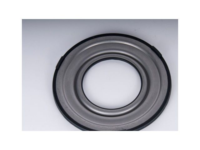
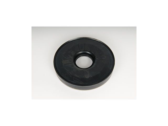
Aftermarket price range: $200-$300 - Auxiliary Transmission Fluid Pump
(OEM #19207983)— This is the least likely cause and should only be replaced after ruling out wiring and control module issues.
Trusted brands: ACDelco (GM Genuine)
OEM price range: $400-$600
Aftermarket price range: $300-$500
Related Codes That Often Appear With This One
- P0C2B — P0C2B (Auxiliary Transmission Fluid Pump Control Module Feedback Signal) is frequently set with P2797 because they both relate to the control and function of the same component. TSB PIP4873A addresses both codes together.
- P0AC4 — P0AC4 (Hybrid Powertrain Control Module Requested MIL Illumination) is a general code indicating the hybrid module has detected a fault and requested the check engine light. It is often seen with P2797 and P0C2B.
Technical Service Bulletins (TSBs) & Recalls
- PIP4873A: States that DTC P2797 (with or without P0C2B) is not likely caused by the auxiliary pump and directs technicians to inspect the wiring between the HPCM and the pump control module. If wiring is good, suspect the module.
- PIT4853D: Notes a potential issue where a misrouted harness can rub on the cooling fins of the Transmission Auxiliary Fluid Pump Control Module, causing wiring damage.
- 19-NA-200: This bulletin addresses P2797 and lists a potential cause as an internal failure of the pump itself. However, it includes a critical note to first inspect the auxiliary pump harness for backed-out or loose terminals on both ends before replacing the pump.
- PIP4833F: Details the specific adapter harnesses required when replacing the auxiliary pump or control module on 2008-2009 models due to connector design changes on newer service parts.
Platform-Specific Known Issues
- A manufacturer TSB (PIP4873A) was issued specifically for the 2009-2013 Escalade Hybrid (and other GM hybrids) to address this code. It strongly advises technicians to inspect the wiring between the HPCM and the pump control module before considering replacing the pump.
- A separate TSB (PIT4853D) for these hybrid models points out a potential wiring harness chafe point against the cooling fins of the Transmission Auxiliary Fluid Pump Control Module.
- The Auxiliary Transmission Fluid Pump Control Module is located in the engine compartment, identified as item #9 in service diagrams, situated amongst other hybrid electronic components.
Mechanic-Grade Diagnostic Values
- Ignition voltage at ATFP control module — expected: 8-18 Volts. Failure: Voltage outside this range indicates a power supply or ground issue.
- Trans. Aux. Oil Pump Control circuit voltage — expected: 11-13 Volts. Failure: Voltage below this range at PIM connector X1, terminal 3 indicates a circuit fault.
- Auxiliary Pump Speed Deviation — expected: Less than 500 RPM difference between commanded and actual speed.. Failure: A difference greater than 500 RPM for over 4 seconds sets DTC P2797.
- ATFP control module circuit board temperature (Warning) — expected: Below 115°C (239°F). Failure: A reading of 115-125°C (239-257°F) indicates an overheat warning.
- ATFP control module circuit board temperature (Fault) — expected: Below 125°C (257°F). Failure: A reading above 125°C (257°F) indicates a severe overheat fault.
- ATFP motor current at start-up — expected: Less than 20 Amps. Failure: Current draw of more than 20 Amps during start-up indicates an 'Over Current' fault, likely a seized pump motor.
Hidden / Shadow Codes Worth Checking
- Aux. Trans. Fluid Pump Fault Status (Parameter): This is a live data parameter on the GM scan tool (GDS2/Tech2) that displays the specific internal fault reported by the ATFP control module. It is more descriptive than the P-code alone. (see via GM GDS2 or equivalent professional scan tool. The parameter will display text values like 'No Fault', 'Over Temperature', 'Over Current', 'Under Voltage', or 'Internal Fault'.)
Scan Tool Commands That Help
- GDS2 / Tech2: Aux. Trans. Pump Speed — Used during diagnosis to command the pump to 50% speed to verify its operation, listen for noise, and compare commanded vs. actual RPM.
- GDS2 / Tech2: Module Programming/Setup — After replacing the Auxiliary Transmission Fluid Pump Control Module (P/N 24261817), a programming or setup procedure is required to ensure it communicates correctly with the vehicle.
Wiring & Ground Locations
- PIM Connector X1, Pin 3 — The Power Inverter Module (PIM) is located in the engine compartment. X1 is one of its main connectors.. This is the specific pin for the 'Trans. Aux. Oil Pump Control' circuit. A technician can test for the required 11-13 volts here to verify the command signal from the HPCM.
- G305 — For hybrid models (RPO HP2), this ground is located under the vehicle to the rear of the left (driver's side) B-pillar, at the third body mount on the frame.. While not directly for the pump module, this is a major body/frame ground for the hybrid system. Poor grounding at this location can cause a variety of difficult-to-diagnose electrical issues in hybrid components.
Real Owner Repair Stories
- Tahoe Yukon Forum user (2008 GMC Yukon Hybrid) — Auto Stop disabled, codes P0C2B and P0AC4 present.
❌ Tried (didn't work) Replaced the auxiliary pump control module with a new one from a 2010 model., Replaced the auxiliary pump itself with a new part.
✅ What actually fixed it The root cause was identified as a physical connector mismatch. The new control module (designed for a 2010 model) had a different connector than the 2008 vehicle's main harness. The shop had an adapter for the pump-to-module connection but was missing the necessary adapter for the vehicle-to-module connection, preventing the new parts from working. The fix required sourcing the correct adapter harness.
OEM Part Supersession History
29543906, 29546431, 29546469, 29546636, 29547550→24261817— Part consolidation and design updates for the Auxiliary Transmission Fluid Pump Control Module.
Heads up: When installing the newer 24261817 module on a 2009 model, specific adapter harnesses are required.N/A→24259588, 24259589, 24259590— Adapter harnesses required to connect newer service parts (pump and module) to the original wiring on 2008-2009 models.
Heads up: Crucial for repairs on 2009 models. TSB PIP4833F specifies which adapter to use: use 24259588 if replacing only the pump, use 24259589 and 24259590 if replacing the control module.
Model Year Variations Within This Range
- 2009: The original factory connectors on the auxiliary pump and control module are different from the connectors on the updated service replacement parts. A TSB (PIP4833F) was issued detailing the specific adapter harnesses required to make the new parts compatible with the 2009 vehicle harness. Failure to use the correct adapter will result in a failed repair.
We Have This Part in Stock


The information in this article is provided for general reference and educational purposes only. Vehicle specifications, procedures, and part compatibility can vary by production date, trim level, and region. Always consult your vehicle's factory service manual and verify part numbers before purchasing or performing repairs. Safety-critical components such as airbags, seat belts, and braking systems should be installed by a qualified professional.
- Cadillac ESCALADE EXT:
- 🧭 Diagnostic Flowchart
- 🛍️ Shop This Part
- What's Unique About the 2009-2013 Cadillac ESCALADE EXT
- Symptoms You May Notice
- Most Likely Causes
- Rare But Worth Checking
- Diagnosis Steps
- Parts You'll Likely Need
- Related Codes That Often Appear With This One
- Technical Service Bulletins (TSBs) & Recalls
- Platform-Specific Known Issues
- Mechanic-Grade Diagnostic Values
- Hidden / Shadow Codes Worth Checking
- Scan Tool Commands That Help
- Wiring & Ground Locations
- Real Owner Repair Stories
- OEM Part Supersession History
- Model Year Variations Within This Range
- 🎟️ Get 5% Off