
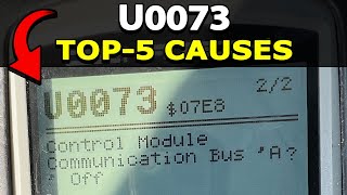
U0073 on 2007-2012 Chevrolet Avalanche: Network Communication Failure Causes and Fixes
On a 2007-2012 Avalanche, code U0073 indicates a severe communication failure on the vehicle's main data network (GMLAN). This is most often caused by a wiring issue, not a failed computer. A critical GM Technical Service Bulletin (TSB #08-07-30-021H) points to corroded or loose terminals in the 16-way transmission wiring connector as a primary culprit. Other common causes include chafed wiring harnesses near the transfer case or fuse block and poor ground connections. The fix is typically a low
- U0073 on your Avalanche is a critical network failure that makes the vehicle unsafe to drive.
- Do not immediately assume a major computer (ECM, TCM) has failed. The problem is far more likely to be in the wiring or connectors.
- The most probable cause, according to a GM TSB, is a bad connection in the large wiring harness plug at the transmission.
- Diagnosis requires a multimeter and a methodical inspection of the wiring harness, starting with the areas identified in GM service bulletins.
- A correct diagnosis will likely lead to a low-cost parts repair, but labor can be significant due to the time it takes to trace the wiring fault.
What's Unique About the 2007-2012 Chevrolet AVALANCHE
The GMT900 platform, which includes the 2007-2012 Avalanche, is known for specific electrical vulnerabilities that cause the U0073 code. A key issue, identified in GM Technical Service Bulletin #08-07-30-021H, is poor connections within the 16-way transmission harness connector (X210). Additionally, these trucks are susceptible to corrosion and chafing in various harness locations, including under the driver's seat, above the transfer case, and near the underhood fuse block, which can bring down the entire communication network. The problem is so frequently a wiring fault that replacing expensive modules without thorough harness diagnostics is a common and costly misdiagnosis.
🎬 Watch: Step-by-step guide to fixing the U0073 communication code.Diagnostic Flowchart
Tap your situation to follow the diagnostic path that matches what you're seeing on this vehicle.
Symptoms You May Notice
- Transmission may not shift or defaults to one gear (often 2nd).
- Multiple warning lights on the instrument panel (Check Engine, ABS, StabiliTrak, Service Hybrid System).
- Instrument panel gauges fluctuate wildly or go dead.
- Intermittent no-crank or no-start condition.
- Engine may stall.
- Door locks cycle intermittently on their own.
- Chimes operate erratically.
- Loss of power window function.
- Driver Information Center (DIC) displays error messages like "Service Traction System".
- Radio and HVAC controls may become inoperative.
- Replacing the Transmission Control Module (TCM) or Engine Control Module (ECM). The U0073 code points to a network-wide failure, which is most often a wiring problem, not a failure of an individual, expensive module.
Most Likely Causes
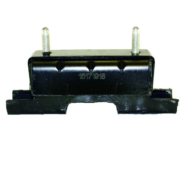
- Backed out or corroded terminals in transmission harness connector (X210) 🔴 High Probability → Shop Transmission Assembly GM TSB #08-07-30-021H specifically identifies the 16-way electrical connector at the transmission as a primary failure point for GMLAN communication issues on this platform. The terminals for the CAN bus wires (often Tan and Tan/Black) can lose tension, corrode, or back out, creating an open circuit that brings the network down.
How to confirm: Visually inspect the large 16-pin connector at the transmission. Check for backed-out pins, corrosion (green or white powder), or a Terminal Position Assurance (TPA) lock that is not fully seated. Wiggle the connector with the engine running to see if symptoms appear or disappear.
Typical fix: Disconnect the battery. Disconnect the connector, clean any corrosion from the terminals using a dedicated contact cleaner, and reseat any backed-out pins. Ensure the TPA lock is fully engaged. Applying dielectric grease before reconnecting can prevent future moisture intrusion.
Est. part cost: $5-$25 - Chafed or broken CAN bus wiring 🟡 Medium Probability Wiring harnesses on these trucks can rub against frame members, brackets, or the transmission/transfer case housing, eventually wearing through the insulation and causing a short or open circuit. Common chafe points are near the transmission bell housing, above the transfer case where the harness can rub a boss, and near the auxiliary fluid pump control module.
How to confirm: Visually inspect the main engine and chassis harnesses, particularly where they route near sharp metal edges or moving parts. You may need to remove plastic conduit to expose the twisted pair of CAN wires (often Tan and Tan/Black) to find the break.
Typical fix: Repair the damaged wires by splicing in a new section of wire using uninsulated butt connectors and heat shrink tubing. The repaired wires should maintain the same length and twist as the original harness to prevent signal interference. Reroute the harness or add protective conduit to prevent future damage.
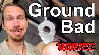
Est. part cost: $10-$30 - Corroded ground connections or fuse block connectors 🟡 Medium Probability GM trucks of this era are known for poor ground connections, especially those exposed to the elements. A poor ground can cause voltage fluctuations that disrupt network communication. Key grounds to inspect are G102 (Engine Block), G300 (Frame), and the connections on the back of the under-hood fuse block (X50A).
How to confirm: Locate, remove, and clean major ground points on the frame and engine block. Inspect the large connectors on the back of the fuse block for looseness or corrosion. Undercoating has been found under the G300 eyelet from the factory, causing a poor connection.
Typical fix: Clean ground connection points to bare metal with a wire brush or sandpaper and re-secure them tightly. Clean and reseat fuse block connectors, applying dielectric grease to prevent future corrosion.
Est. part cost: $0-$15 - Weak or failing battery / poor charging system ⚪ Low Probability → Shop Vehicle Battery While not specific to this truck, all control modules require stable voltage (typically above 12.4V) to communicate properly. A weak battery, failing alternator, or poor battery cable connections can cause modules to drop off the network, especially during engine cranking in cold weather.
How to confirm: Test the battery voltage with the vehicle off (should be above 12.4V) and while running (should be 13.7V-14.7V). A load test at an auto parts store is the most definitive way to check battery health.
Typical fix: Charge or replace the battery. Test the alternator and replace it if it is failing. Clean and tighten all battery terminals and ground connections.
Est. part cost: $150-$400
Rare But Worth Checking
- Faulty terminating resistor: The CAN bus has two 120-ohm resistors. On this platform, one is internal to the ECM, and the other is a separate resistor located in the chassis harness, often near the rear of the vehicle or Trailer Brake Control Module (TBCM). If one fails, the total bus resistance will change from 60 ohms to 120 ohms, causing communication to stop. This is a key part of electrical diagnosis.
- Failed control module: A single module (e.g., BCM, EBCM, TCM, or TBCM) can short internally and pull the entire network down. This is rare and should only be considered after all wiring and connection issues have been ruled out. A common diagnostic technique is to disconnect modules one by one to see if the 60-ohm bus resistance returns.
- Aftermarket device interference: Improperly installed remote starters, alarms, trailer brake controllers, or even OBD-II plug-in insurance/fleet trackers can tap into the CAN bus incorrectly and cause network errors.
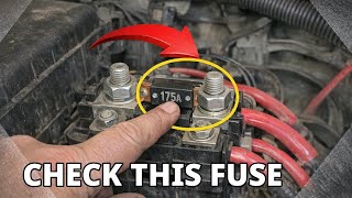
- Blown 175A Mega Fuse: A voltage spike from an improper jump start can blow the 175-amp mega fuse located on the battery distribution block. This will cut power to critical modules and take the high-speed CAN network offline, causing a U0073 code.
Diagnosis Steps
- Check Battery and Fuses: Ensure the battery is fully charged (12.4V+ engine off) and the charging system is working (13.7-14.7V engine on). Check all fuses related to the ECM, TCM, and BCM in both the underhood and instrument panel fuse boxes.
- Scan for All Codes: Use a scan tool capable of reading codes from all modules (not just the engine). Note which modules are not communicating. This can provide clues to the location of the fault.
- Check CAN Bus Resistance: With the battery disconnected, use a multimeter to measure the resistance between Pin 6 (CAN High) and Pin 14 (CAN Low) at the OBD-II port. A healthy network should read approximately 60 ohms. A reading of 120 ohms indicates an open circuit or a bad terminating resistor. A reading near 0 ohms indicates a short between the two CAN wires.
Parts You'll Likely Need
- Wiring Harness Repair Supplies (butt connectors, heat shrink, wire)
- Electrical Contact Cleaner
- Transmission Harness Connector Pigtail
- Battery
Related Codes That Often Appear With This One
- U0100 — Lost Communication With ECM/PCM. This code sets when other modules can't hear from the engine computer, a direct result of the U0073 network failure.
- U0101 — Lost Communication With TCM. This code sets when other modules can't hear from the transmission computer, which is why the transmission may not shift.
- U0121 — Lost Communication With Anti-Lock Brake System (ABS) Control Module. This code sets when the ABS module goes offline, disabling ABS and StabiliTrak.
- U0140 — Lost Communication With Body Control Module (BCM). This code sets when the BCM goes offline, causing issues like erratic door locks and chimes.
- P0700 — Transmission Control System (MIL Request). This is a generic code set by the TCM to tell the ECM to turn on the check engine light, often triggered by the underlying U0101/U0073 communication loss.
Technical Service Bulletins (TSBs) & Recalls
- 08-07-30-021H: The primary TSB for this issue, covering loss of GMLAN communication, various symptoms, and pointing to the transmission connector, chafed wiring, and poor grounds as root causes.
Platform-Specific Known Issues
- Technical Service Bulletin #08-07-30-021H directly addresses the U0073 code and related communication failures on this platform. It guides technicians to inspect the transmission harness connector, check for chafed wiring, and look for corrosion in module connectors before replacing any major parts.
Mechanic-Grade Diagnostic Values
- GMLAN (CAN Bus) Resistance — expected: ~60 Ohms. Failure: A reading of ~120 Ohms suggests an open circuit or a failed terminating resistor. A reading near 0 Ohms indicates a short circuit between the CAN High and CAN Low wires.
- Battery Voltage (Static) — expected: 12.4V or higher. Failure: Voltage below 12.4V indicates a discharged or failing battery, which can cause modules to drop off the network.
- Charging System Voltage — expected: 13.7V - 14.7V. Failure: Voltage outside this range indicates a potential alternator or charging system fault, leading to unstable power for control modules.
Scan Tool Commands That Help
- GDS2 (GM Global Diagnostic System 2): Data Bus Diagnostic Tool — This is a guided diagnostic routine within the factory scan tool, available since 2015, designed to help technicians systematically diagnose High Speed LAN issues by checking module status and network integrity.
- Professional Scan Tool (e.g., Tech2, Autel, etc.): Module Status Check / Network Scan — Use this function at the beginning of the diagnosis to get a list of all control modules on the vehicle and see which ones are not communicating. This helps narrow down the location of the network fault.
Wiring & Ground Locations
- G102 — At the left rear of the engine block.. This ground is critical for the Engine Control Module (ECM) and Transmission Control Module (TCM). A poor connection here can cause both modules to lose communication.
- G103 — On the cowl in the left rear of the engine compartment, typically above the brake booster.. This ground serves the Body Control Module (BCM), Instrument Panel Cluster (IPC), and the Data Link Connector (DLC) itself. A fault here can cause widespread chaos and prevent a scan tool from communicating.
- G218 — Under the driver's side dash, often behind the kick panel.. This is a major instrument panel and body harness ground point. It is a well-known failure point on GMT900 trucks for causing various electrical and communication issues.
- G300 — Under the vehicle near the driver's door, often on a body mount.. This ground is notorious for having undercoating sprayed on it from the factory, creating a poor, high-resistance connection that can disrupt module communication. It must be removed and cleaned to bare metal.
- X50A — The main connector block on the underside of the Underhood Fuse Block.. This is a major junction for power and data signals. Corrosion or backed-out terminals in this large connector block can sever communication to multiple modules at once, triggering a U0073.
- Terminating Resistor #2 — Not internal to the ECM. It is a separate 120-ohm resistor located in the chassis harness, often near the Trailer Brake Control Module (TBCM) or at the physical end of the bus near the rear of the vehicle.. If this resistor fails or its wiring is damaged, the total bus resistance will read 120 ohms instead of 60, and all high-speed communication will cease.
Real Owner Repair Stories
- silveradosierra.com forum user (2007.5 Chevrolet Silverado 2500HD (GMT900 Platform Mate)) — Service StabiliTrak, Service Trailer Brake, Check Engine lights on. Codes U0073, U0100, U0101, U0121, U0140.
❌ Tried (didn't work) Initial diagnosis focused on wiring harnesses and grounds without a clear fault found.
✅ What actually fixed it The Trailer Brake Control Module (TBCM) had failed internally and was shorting out the CAN bus. Unplugging the TBCM immediately restored communication between all other modules and the vehicle returned to normal operation. The TBCM was then replaced. - CorvetteForum Discussion (2008 Corvette (Shares TSB #08-07-30-021H with Avalanche)) — P0700 and U0073, gauge cluster goes crazy, "Service Traction System" message, transmission stuck in gear.
❌ Tried (didn't work) Clearing codes would only work temporarily.
✅ What actually fixed it The user noted that many technicians replace the TCM or BCM multiple times, and the problem is 'fixed' on the second or third try. The user's insight was that the real fix was likely the repeated unplugging and replugging of the harness connectors, which finally established a good connection on a previously loose or corroded pin.
"I Checked Everything" — The Actual Cause
- The electrical equivalent of this is when wiring continuity tests pass, but the fault persists. A common cause is a single control module, like the Trailer Brake Control Module (TBCM), failing internally and shorting the data bus. The wiring itself is fine, but the module disrupts all communication. The fix is to unplug modules one by one until communication is restored.
- Another example is finding factory undercoating between the ground eyelet and the frame at ground G300. A visual inspection might show the ground is attached, but electrically it has high resistance. The ground must be unbolted, cleaned to bare metal, and re-secured.
OEM Part Supersession History
TSB #08-07-30-021G (and earlier)→TSB #08-07-30-021H— The technical service bulletin for this issue has been revised multiple times to add model years and update diagnostic information as more common failure points were identified.
Model Year Variations Within This Range
- 2007-2014: For diagnostics performed after 2015, GM service information includes a "Data Bus Diagnostic Tool" in the GDS2 scan tool software. This provides a guided diagnostic flow that was not available to technicians in earlier years, who had to rely more on manual resistance and voltage checks.
Helpful Videos


We Have This Part in Stock

The information in this article is provided for general reference and educational purposes only. Vehicle specifications, procedures, and part compatibility can vary by production date, trim level, and region. Always consult your vehicle's factory service manual and verify part numbers before purchasing or performing repairs. Safety-critical components such as airbags, seat belts, and braking systems should be installed by a qualified professional.
- Chevrolet AVALANCHE:
- 🧭 Diagnostic Flowchart
- 🎬 Helpful Videos
- 🛍️ Shop This Part
- What's Unique About the 2007-2012 Chevrolet AVALANCHE
- Symptoms You May Notice
- Most Likely Causes
- Rare But Worth Checking
- Diagnosis Steps
- Parts You'll Likely Need
- Related Codes That Often Appear With This One
- Technical Service Bulletins (TSBs) & Recalls
- Platform-Specific Known Issues
- Mechanic-Grade Diagnostic Values
- Scan Tool Commands That Help
- Wiring & Ground Locations
- Real Owner Repair Stories
- "I Checked Everything" — The Actual Cause
- OEM Part Supersession History
- Model Year Variations Within This Range
- 🎟️ Get 5% Off