
U0073 on 2009-2014 Ford F-150: Causes and Fixes for Communication Bus Failure
On a 2009-2014 F-150, code U0073 is most often caused by cracked solder joints on the instrument cluster's main connector. This is a common, well-documented failure that causes a no-start and erratic dash lights. The fix is to remove the cluster and re-solder the connector pins, which is a low-cost DIY repair. Other common causes include a leaking transmission bulkhead connector and corroded body grounds.
- For a 2009-2014 F-150, a U0073 code with a dead instrument cluster and a no-start condition almost always points to failed solder joints on the back of the cluster.
- Before suspecting expensive modules, perform the 'wiggle test' on the instrument cluster's main connector.
- If the truck also has transmission-related codes (U0100, U0101), inspect the transmission bulkhead connector for fluid leaks.
- Always check the battery and major ground straps before diving into complex wiring diagnostics.
What's Unique About the 2009-2014 Ford F-150
For the 12th generation F-150 (2009-2014), the U0073 code is very frequently traced back to a specific manufacturing defect: cracked solder joints on the main electrical connector of the instrument panel cluster (IPC). Over time and with vibration, these connections fail, causing the cluster to lose communication and bring down the entire network. While other causes like wiring damage or module failure are possible, the instrument cluster is a well-known weak point for this exact code and set of symptoms on this truck, a fact widely discussed in owner forums.
Symptoms You May Notice
- No-crank, no-start condition.
- Multiple warning lights on the dashboard are flashing or on solid (Check Engine, ABS, wrench light, etc.).
- Odometer displays dashes ('-------') instead of mileage.
- Gauges (speedometer, tachometer) drop to zero or behave erratically.
- Inability to communicate with the vehicle using an OBD-II scan tool.
- Transmission may be stuck in one gear ('limp mode').
- Anti-theft light (PATS) flashes rapidly, indicating a communication failure with the PCM or cluster.
- Message center may display warnings like 'CHECK BRAKE SYSTEM' or 'TRAILER BRAKE MODULE FAULT'.
- Loss of power to A/C controls or radio display.
- Replacing the PCM (Powertrain Control Module) without confirming it is the source of the network failure. The PCM is expensive and often blamed incorrectly when the issue is a simple wiring, ground, or instrument cluster problem.
- Replacing the battery without diagnosing a charging system or parasitic draw issue that caused the battery to fail.
- Replacing the transmission lead frame when only the inexpensive bulkhead connector sleeve was leaking.
Most Likely Causes
- Cracked Solder Joints on Instrument Panel Cluster (IPC) 🔴 High Probability → Shop Instrument Cluster This is a widely documented failure point for the 2009-2014 F-150 generation. The solder connections for the main harness connector on the cluster's circuit board crack over time, causing an intermittent or total loss of communication.
How to confirm: With the key on, access the rear of the instrument cluster and gently wiggle the main electrical connector. If the dashboard lights and gauges flicker or return to normal as you move the plug, the solder joints are the problem. Visually, the pins may appear to move slightly within their solder pads when wiggled.
Typical fix: Remove the instrument cluster, disassemble it to access the circuit board, and re-solder all the pins for the main connector using fresh solder. Many YouTube videos demonstrate this process. Alternatively, send the cluster to a specialized electronics repair service or replace it with a new/refurbished unit, which requires programming.
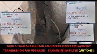
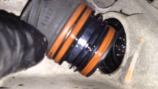
Est. part cost: $0 (for solder) - $400 (for a replacement cluster) - Leaking Transmission Bulkhead Connector Sleeve 🟡 Medium Probability → Shop Transmission Assembly The o-rings on the 6R80 transmission's electrical bulkhead connector sleeve can fail, allowing transmission fluid to wick up into the connector pins. This contaminates the connection, disrupting HS-CAN communication with the Transmission Control Module (TCM) and often triggering U0073, U0100, and U0101 codes. TSB 11-3-25 was issued for this problem. 🎬 Watch: Step-by-step bulkhead sleeve replacement and transmission pan upgrade guide.
How to confirm: Visually inspect the main round electrical connector on the passenger side of the transmission. If transmission fluid is present inside the connector when unplugged, the sleeve is leaking. 🎬 See this walkthrough on repairing a leaking transmission bulkhead sleeve.
Typical fix: Drop the transmission pan, release the internal locking tab for the bulkhead sleeve, and install a new sleeve. The updated part uses black o-rings instead of the original orange ones. Clean the harness connector thoroughly with electrical contact cleaner before reconnecting. This is often done during a transmission fluid and filter service.
Est. part cost: $20-$40 - Corroded or Broken Ground Wires 🟡 Medium Probability Owners have reported finding the main cab-to-frame ground strap, often located on the passenger side frame rail near the catalytic converter, completely rusted through or broken. A poor ground can cause unstable voltage across the network, leading to module communication dropouts. Other key grounds are near the battery and on the fender aprons.
How to confirm: Visually inspect all major ground points between the engine, body, and frame for corrosion or physical damage. Pay close attention to the ground strap on the passenger side frame rail. A voltage drop test from the battery negative post to the component body can confirm a bad ground.
Typical fix: Clean the contact points to bare metal and re-secure the ground. If the strap or cable is broken, replace it with a heavy-gauge equivalent.
Est. part cost: $15-$50 - Damaged CAN Bus Wiring ⚪ Low Probability A known chafe point exists where the main harness runs near the parking brake mechanism in the driver's footwell. Vibration can cause the harness to rub against the metal bracket, eventually damaging the CAN wires.
How to confirm: Visually inspect the CAN bus wiring harnesses (twisted pair, often Grey/Orange and Violet/Orange) for signs of chafing, rodent damage, or corrosion, particularly near the parking brake, fuse box, and firewall. A multimeter can be used to check for resistance between the two CAN wires at the DLC (pins 6 and 14); it should be ~60 ohms with the battery disconnected.
Typical fix: Repair the damaged section of wire. This requires carefully splicing, soldering, and heat-shrinking the new wire section to maintain signal integrity. The twisted-pair nature of the wires must be preserved.
Est. part cost: $5-$25
Rare But Worth Checking
- Weak or Failing Battery: → Shop Vehicle Battery While less common as the root cause for a persistent U0073, low system voltage during cranking can cause modules to fail their initialization, temporarily triggering this code. Always verify battery health (at least 12.4V) and charging system function first.
- Faulty Control Module: A single module (like the ABS, BCM, or even the ACM/Radio) can fail internally and broadcast noise or stop communicating, disrupting the entire network. This is typically diagnosed by a professional using a scan tool to see which modules are offline, and then disconnecting the suspect module to see if communication is restored.
- Faulty Smart Junction Box (SJB) / Body Control Module (BCM): → Shop Body Control Module The SJB/BCM acts as a gateway between different CAN buses. Water intrusion (from a leaking windshield or sunroof drains) or internal failure of the SJB can cause widespread communication issues, including U0073.
Diagnosis Steps
- Check the battery and charging system. Ensure the battery has at least 12.4 volts with the engine off and that the alternator is charging correctly (13.8-14.5V when running).
- Attempt to read codes with an OBD-II scanner. Note if the scanner fails to connect, which is a key symptom of a downed CAN bus.
- Perform the 'wiggle test'. With the key on, gently wiggle the main connector at the back of the instrument cluster. If the dash lights flicker or gauges respond, the cluster solder joints are the cause.
- Inspect the transmission bulkhead connector on the passenger side of the 6R80 transmission for any signs of fluid leakage. Unplug it and check for fluid inside the connector.
- Inspect major ground connections. Check the cab-to-frame ground on the passenger side frame rail for rust or damage. Also check grounds near the battery and in the passenger kick panel.
- Inspect for wiring damage. Pull back the carpet and trim near the driver's side parking brake assembly and look for any chafed wires in the main harness.
- Check CAN bus resistance. With the battery disconnected, use a multimeter to measure resistance between Pin 6 (CAN-H) and Pin 14 (CAN-L) of the OBD-II port. A healthy network should read approximately 60 Ohms. A reading of 120 Ohms suggests an open in one of the two terminating resistors (often in the PCM or IPC), while a reading near 0 Ohms indicates a short between the two CAN wires.
Parts You'll Likely Need
- Instrument Panel Cluster — The most common cause is failed solder joints on the cluster's circuit board. Often repaired rather than replaced.
- Transmission Bulkhead Connector Sleeve
(OEM #AL3Z-7G276-A / AL3Z-7G276-D)— The o-rings on the original sleeve fail, causing fluid to leak into the electrical connector and disrupt communication. - Ground Strap — The cab-to-frame ground strap is exposed to the elements and can rust through, causing an open ground connection.
- Solder and Soldering Iron — Required for the DIY repair of the instrument cluster solder joints.
Related Codes That Often Appear With This One
- U0100 — Lost Communication With ECM/PCM. This code often appears with U0073 when the transmission bulkhead connector is leaking or the cluster fails, as the TCM or other modules lose their connection to the PCM.
- U0101 — Lost Communication with TCM. This is another common code seen alongside U0073, specifically pointing to the transmission communication failure, often due to the leaking bulkhead sleeve.
- U0140 — Lost Communication With Body Control Module. If the BCM/SJB or its wiring is the source of the network problem, this code will likely be present.
- U0155 — Lost Communication With Instrument Panel Cluster (IPC) Control Module. This code is a strong indicator that the fault lies with the instrument cluster itself, corroborating the common solder joint failure.
Technical Service Bulletins (TSBs) & Recalls
- TSB 11-3-25: Addresses transmission fluid leakage from the bulkhead connector sleeve on 2009-2010 F-150s and other models with the 6R80 transmission. This leak is a known cause of communication codes like U0073.
Platform-Specific Known Issues
- Instrument Cluster Connector Solder Failure: → Shop Instrument Cluster The most prevalent issue for the 2009-2014 F-150. The solder joints for the main connector on the cluster's printed circuit board (PCB) crack from thermal cycles and vibration. This creates an open circuit on the HS-CAN bus, which runs through the cluster, effectively shutting down communication between all major modules. The fix is to reflow the solder on all pins of the connector.
- Wiring Harness Chafe Near Park Brake Pedal: Several owners have discovered the main wiring harness that runs along the driver's side floor and up into the dash can rub against the parking brake pedal assembly. Over time, this can wear through the insulation of the CAN bus wires (typically a twisted pair of Grey/Orange and Violet/Orange wires), causing them to short to each other or to ground, triggering the U0073 code.
Mechanic-Grade Diagnostic Values
- HS-CAN Bus Resistance — expected: ~60 Ω. Failure: A reading of ~120 Ω indicates an open circuit or a faulty terminating module. A reading near 0 Ω indicates a short between the CAN High and CAN Low wires.
- HS-CAN Bus Voltage (Key On, Engine Off) — expected: CAN-High (Pin 6 to Ground): ~2.5V to 3.5V. CAN-Low (Pin 14 to Ground): ~1.5V to 2.5V.. Failure: Voltages outside these ranges, or a flatline on either wire, indicates a short to power, short to ground, or an open circuit.
- Continuity from DLC to PCM — expected: < 5.0 Ω. Failure: An open or high resistance reading (O.L.) indicates a break in the wire between the diagnostic port and the PCM.
Scan Tool Commands That Help
- Ford IDS (Integrated Diagnostic System): Network Test / Self Test — This is the primary professional diagnostic step. The tool attempts to communicate with every module on the network and provides a list of which modules are responding and which are not. This quickly isolates the area of the network that has failed.
- Ford IDS (Integrated Diagnostic System): Module Programming / PMI (Programmable Module Installation) — This function is required after replacing a major control module such as the PCM, IPC, or BCM. It loads the vehicle's specific 'as-built' data and software into the new module to ensure it functions correctly.
- FORScan: IPC Module Configuration — When swapping an instrument cluster (e.g., upgrading or replacing a failed unit), FORScan can be used to write the original vehicle's 'as-built' data to the replacement cluster, which is necessary to ensure all features and the odometer work correctly.
Wiring & Ground Locations
- G201 / G200 — Passenger side kick panel area, near the Body Control Module (BCM).. This is a major ground point for several interior modules, including the BCM/SJB. Corrosion here due to water leaks from the windshield or sunroof is a known cause of various network issues.
- Main Frame Ground — Passenger side frame rail, often near the catalytic converter.. This is the primary cab-to-frame ground. It is highly susceptible to rust and can break completely, causing unstable voltage and widespread communication failures.
- C2280B — This is one of the main connectors for the Body Control Module (BCM), located in the passenger kick panel.. The BCM acts as a gateway between different networks. A poor connection, corrosion from water intrusion, or a backed-out pin at this connector can sever communication, triggering a U0073.
- DLC (OBD-II Port) Pins — Under the driver's side dashboard.. Pins 6 (CAN-H) and 14 (CAN-L) are the direct access points for testing the HS-CAN network's voltage and resistance.
Real Owner Repair Stories
- CarKiller forum user (2010 Ford F-150 5.4L) — No crank, no start, rapidly flashing anti-theft light. Initial code U0100. Inability to communicate with PCM.
❌ Tried (didn't work) Replaced the PCM and programmed two new keys., Swapped in a used instrument cluster.
✅ What actually fixed it The owner performed a resistance test and found 120 Ohms instead of 60. Further testing revealed an open circuit (no continuity) on the CAN-L wire between Pin 14 of the OBD-II port and Pin 43 of the PCM connector. The fix was to find and repair the break in that specific wire. - F150forum.com user (2015 Ford F-150 (concept applies to 2009-2014)) — Constant 'Trailer Disconnected' messages on the dash when towing a single-axle trailer with electric brakes. Brakes would not activate via the integrated trailer brake controller (TBC).
❌ Tried (didn't work) Dealer replaced trailer wiring and junction box., Dealer performed a software update to the TBC., Dealer tested with other trucks, blamed the trailer.
✅ What actually fixed it The owner determined the factory TBC was not sensing the low electrical load from the single-axle brakes. He wired a load resistor in parallel with the trailer's brake circuit to increase the total resistance to 6 ohms. This allowed the truck's TBC to properly detect the trailer and activate the brakes, resolving the communication error messages.
"I Checked Everything" — The Actual Cause
- A common scenario for U0073 is when all factory wiring and modules appear to be functioning correctly, but the fault persists. In these cases, the root cause is often an improperly installed aftermarket accessory. Devices like remote starters, aftermarket stereos, or GPS trackers that are incorrectly tapped into the CAN bus wires can corrupt the network data, causing modules to drop out and triggering the code. The fix is to disconnect the aftermarket device entirely to see if communication is restored, and then wire it correctly or remove it.
OEM Part Supersession History
AL3Z-7G276-A→AL3Z-7G276-D— The original transmission bulkhead connector sleeve used orange o-rings that were prone to leaking. The updated part uses improved black o-rings to provide a better seal against transmission fluid intrusion.Varies (e.g., 9L3Z-10849-N for 2009 Platinum)→Varies (e.g., CL3Z-10849-RA for 2012 Platinum)— Instrument cluster part numbers changed frequently based on model year, trim level (XL, XLT, Lariat, Raptor), and feature set (e.g., with/without Select Shift).
Heads up: A replacement cluster must match the vehicle's transmission type (Select Shift vs. non-Select Shift). After physical installation, the cluster must be programmed with the vehicle's original 'as-built' data using a tool like FORScan or Ford IDS to ensure the odometer, gauges, and all features work correctly.
Model Year Variations Within This Range
- 2011-2012: Ford issued TSB 13-1-7 for some 2011-2012 F-150s with 3.5L and 3.7L engines for harsh shifting concerns. The fix was a PCM software update. This indicates that module software was actively being revised during this period, and ensuring modules have the latest calibration can be a relevant step in resolving communication-related issues.
- 2009-2014: The instrument cluster design and part numbers are highly specific to the year and trim level. For example, a cluster from an XLT is different from a Platinum or SVT Raptor. This is critical when sourcing a replacement, as a mismatched cluster may not be compatible or may require extensive programming.
Diagnostic Flowchart
Real Owner Stories
Aggregated from forums and TSBs cited above. Mileages and costs reflect what owners reported in those sources.
2010 Ford F-150 XLT 4.6L
Symptoms: Experienced a sudden no-crank, no-start condition accompanied by the U0073 communication code.
What fixed it: Diagnosed as a communication failure preventing the vehicle from cranking.
Source hint: f150forum.com thread titled '2010 F-150 XLT 4.6L VIN 8 U0073 no start no crank'
2010 Ford F-150
Symptoms: Vehicle threw a U0073 code due to a shorted instrument cluster, causing network communication failure.
What fixed it: Repaired the shorted instrument panel cluster to restore CAN bus communication.
Source hint: YouTube video titled '2010 F-150...Fixing U0073 Code and shorted Cluster'
2009-2014 Ford F-150 (6R80 Transmission)
Symptoms: Triggered U0073, U0100, and U0101 codes simultaneously due to transmission communication loss.
What fixed it: Replaced the leaking 6R80 transmission bulkhead sleeve to stop fluid from contaminating the electrical connector.
Source hint: YouTube video titled 'U0073 U0100 U0101 FORD F-150 6R80 BULKHEAD SLEEVE REPLACEMENT'
2009-2014 Ford F-150
Symptoms: Code U0073 appeared on the scanner, and the truck was completely unresponsive with a no-crank, no-start condition.
What fixed it: Addressed the underlying CAN bus communication failure.
Source hint: Reddit r/f150 thread titled 'Code U0073 appeared no crank no start please help'
Documented NHTSA Reports
While the F-150 is the primary focus, manufacturer records across the Ford platform highlight the severity of this code. For instance, NHTSA ODI #11549596 describes a diagnostic report for a Ford vehicle where U0073 was identified as "Control module communication bus A off" with a "Bus off" failure type, illustrating how this code signifies a complete communication shutdown on the network.
Related OBD-II Codes
Frequently Asked Questions
Is there a TSB for the U0073 code on my 2009-2014 F-150?
Why does my F-150 odometer show dashes ('-------') and refuse to crank?
How can I test if my instrument cluster is causing the U0073 code?
Where should I look for wiring damage that causes U0073 on these trucks?
What is the updated part number for the leaking transmission bulkhead sleeve?
Helpful Videos
We Have This Part in Stock


The information in this article is provided for general reference and educational purposes only. Vehicle specifications, procedures, and part compatibility can vary by production date, trim level, and region. Always consult your vehicle's factory service manual and verify part numbers before purchasing or performing repairs. Safety-critical components such as airbags, seat belts, and braking systems should be installed by a qualified professional.
- Ford F-150:
- 🧭 Diagnostic Flowchart
- 🎬 Helpful Videos
- 🛍️ Shop This Part
- What's Unique About the 2009-2014 Ford F-150
- Symptoms You May Notice
- Most Likely Causes
- Rare But Worth Checking
- Diagnosis Steps
- Parts You'll Likely Need
- Related Codes That Often Appear With This One
- Technical Service Bulletins (TSBs) & Recalls
- Platform-Specific Known Issues
- Mechanic-Grade Diagnostic Values
- Scan Tool Commands That Help
- Wiring & Ground Locations
- Real Owner Repair Stories
- "I Checked Everything" — The Actual Cause
- OEM Part Supersession History
- Model Year Variations Within This Range
- Real Owner Stories
- 2010 Ford F-150 XLT 4.6L
- 2010 Ford F-150
- 2009-2014 Ford F-150 (6R80 Transmission)
- 2009-2014 Ford F-150
- Documented NHTSA Reports
- Related OBD-II Codes
- Frequently Asked Questions
- 🎟️ Get 5% Off