
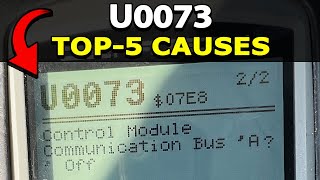
U0073 on 2007-2011 GMC Yukon Denali XL: Causes for Control Module Communication Failure
U0073 on a 2007-2011 GMC Yukon Denali XL indicates a total communication failure on the vehicle's high-speed data network (GMLAN). The most common causes are wiring issues, such as backed-out terminals in the transmission connector or corroded wires under the driver's side carpet due to water leaks. Other frequent culprits include a faulty control module (like the EBCM or BCM) or poor ground connections. This is a complex electrical issue, not a simple part replacement.
- U0073 is a critical network failure, not a simple sensor issue. Do not continue to drive the vehicle.
- The most likely causes are physical wiring problems: backed-out pins at the transmission connector or corrosion under the driver's side carpet.
- Always check the battery and perform a thorough visual inspection of known problem areas before assuming a costly control module has failed.
- Diagnosis is complex and best left to a professional with network diagnostic tools unless you find an obvious wiring fault.
What's Unique About the 2007-2011 Gmc YUKON DENALI XL
The GMT900 platform, which this Yukon is built on, has a complex and widely distributed data network. A key vulnerability, identified in GM Technical Service Bulletin #08-07-30-021H, is the tendency for terminals to back out of the main transmission harness connector, causing a loss of communication with the TCM that can bring down the entire network. Additionally, these trucks are known for water leaks into the cabin (from sunroof drains, windshield seals, or roof racks), which can corrode critical CAN bus wiring and junction blocks located under the driver's side carpet and kick panel. While Splice Pack SP205 is in this area, it serves the Class 2 data bus; the issue for U0073 is corrosion on the GMLAN twisted pair wires (typically Tan and Tan/Black) that run through the same harness channel.
Diagnostic Flowchart
Tap your situation to follow the diagnostic path that matches what you're seeing on this vehicle.
Symptoms You May Notice
- Multiple warning lights on the instrument panel (Check Engine, ABS, Stabilitrak, Traction Control).
- Transmission may not shift, shift harshly, or be stuck in one gear (limp mode).
- Instrument panel gauges fluctuating erratically or dropping to zero.
- Intermittent door locks cycling or chimes sounding for no reason.
- Engine may stall, run rough, or fail to start.
- Loss of power steering assist (if equipped with electronic power steering).
- Driver Information Center (DIC) displaying various error messages like 'Service Stabilitrak' or 'Service Traction Control'.
- Scan tool is unable to communicate with multiple control modules.
- Replacing the Transmission Control Module (TCM) or Engine Control Module (ECM) without first confirming the wiring and connectors are intact. The problem is very often in the wiring leading to the module, not the module itself.
Most Likely Causes
- Backed-out Terminals in Transmission Harness Connector 🔴 High Probability → Shop Transmission Assembly This is a well-documented issue on the GMT900 platform, specifically cited in TSB #08-07-30-021H. Vibration and heat cycles can cause the CAN bus terminals within the 16-way transmission connector to work themselves loose.
How to confirm: Visually inspect the 16-way electrical connector at the transmission. Check if the Terminal Position Assurance (TPA) lock is fully seated. Carefully check if the two CAN bus wires (typically a twisted pair) have backed out of the connector body.
Typical fix: Re-seat the loose terminals firmly into the connector and ensure the TPA lock is fully engaged. Applying a small amount of dielectric grease can help prevent future corrosion and moisture intrusion.
Est. part cost: $0-$15 - Corroded or Damaged CAN Bus Wiring 🔴 High Probability Water leaks from the windshield, sunroof, or roof rack can allow water to pool under the driver's side carpet and door sill plate. This area contains a major wiring harness for the CAN bus, which is highly susceptible to corrosion.
How to confirm: Pull up the driver's side door sill plate and lift the carpet to inspect the wiring harness for signs of green or white corrosion ('green crusties'), moisture, or physical damage. The CAN wires are typically a twisted pair of Tan and Tan/Black wires.
Typical fix: The damaged section of wire must be cut out, and a new piece of wire must be spliced in using environmentally-sealed butt connectors or solder and heat shrink tubing. Corroded connectors or junction blocks must be cleaned or replaced.
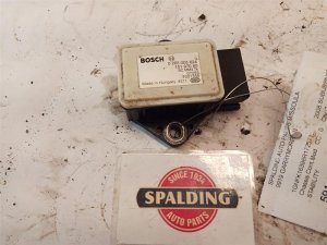
Est. part cost: $10-$50 - Faulty Control Module 🟡 Medium Probability Any module on the high-speed CAN bus can fail internally and either stop communicating or flood the network with corrupt data, bringing the entire bus down. The EBCM (ABS module), BCM, and even the Fuel Pump Control Module (FPCM) are documented points of failure on this platform.
How to confirm: This requires a process of elimination with a professional scan tool. A technician will unplug modules one by one from the network to see if communication is restored to the remaining modules. If unplugging a specific module (e.g., the EBCM) allows the network to come back online, that module is the culprit.
Typical fix: Replace the faulty control module. The new module will likely require programming to the vehicle's VIN, which often requires dealer-level software (like a Tech2/MDI).
Est. part cost: $250-$800 - Poor Ground Connection 🟡 Medium Probability Body and engine grounds on GMT900 trucks are known to loosen or corrode, causing intermittent voltage issues for control modules that can disrupt network communication. TSB PIT5405C specifically identifies ground G218 as a culprit.
How to confirm: Locate and inspect major ground points, particularly G218 (behind the driver's kick panel), G300 (under the vehicle at the driver's door on a body mount), and G102 (driver's side of engine). Ensure they are clean, tight, and free of corrosion.
Typical fix: Remove the ground bolt, clean the contact surfaces of the terminal and the chassis down to bare metal, and re-secure the connection tightly. Apply a corrosion inhibitor to prevent future issues.
Est. part cost: $0-$5
Rare But Worth Checking
- Faulty Aftermarket Electronics: Improperly installed remote starters, alarms, stereos, or even faulty phone chargers plugged into a power outlet can introduce electrical noise or shorts that bring down the network.
- Rodent Damage: Mice or other rodents can chew on wiring harnesses, causing shorts or open circuits in the CAN bus wires, which are often routed along frame rails or through the firewall.
Diagnosis Steps
- Verify the battery is fully charged (above 12.4V) and the charging system is working correctly (13.7-14.7V when running). Low or unstable voltage is a common cause of communication errors.
- Use a professional scan tool to confirm U0073 is present 🎬 Watch: A deep dive into diagnosing GMC CAN bus codes. and see which other 'U' codes are stored. Attempt to communicate with all major modules (ECM, TCM, BCM, EBCM, FPCM, TCCM). Note which ones are not responding. 🎬 See how to troubleshoot lost communication codes on Chevy trucks.
- Inspect the 16-way electrical connector at the transmission for backed-out pins or a loose TPA lock, as detailed in TSB #08-07-30-021H.
- Pull up the driver's side door sill and carpet. Inspect the wiring harnesses in that channel for any signs of water intrusion or green/white corrosion on the twisted pair of GMLAN wires.
- If no visible damage is found, measure the resistance between Pin 6 (CAN High) and Pin 14 (CAN Low) at the OBD-II port with the battery disconnected. A healthy network should read approximately 60 ohms. A reading of 120 ohms indicates an open circuit or a failed termination resistor in one of the main modules (like the ECM or EBCM). A reading near 0 ohms indicates a short between the two CAN wires.
- If resistance is incorrect (120 ohms or 0 ohms), begin unplugging modules one by one from the high-speed CAN bus. After unplugging each module, re-check the resistance. When the resistance returns to a normal value, the last module unplugged is likely the source of the fault.
- Inspect major ground connections for tightness and corrosion, especially G218 (driver kick panel), G300 (frame), and G102 (engine).
Parts You'll Likely Need
- Wiring Repair Supplies — Used to repair corroded or broken CAN bus wires found under the carpet or near connectors.
Trusted brands: 3M
Aftermarket price range: $10-$30 - Transmission Connector Pigtail
(OEM #88862231)— To replace a damaged or corroded 16-way transmission harness connector if the terminals cannot be repaired. This part is also known by the ACDelco number PT2312.
Trusted brands: ACDelco
OEM price range: $40-$70
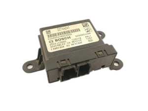
Aftermarket price range: $25-$50 - Body Control Module (BCM)
(OEM #22860591)— The BCM is a common module to fail and bring down the network. Part numbers are VIN-specific; always verify. This part number supersedes many others. Requires programming.
Trusted brands: ACDelco (Genuine GM)
OEM price range: $250-$400
Aftermarket price range: $200-$350 - Electronic Brake Control Module (EBCM) — The EBCM is another common failure point and contains one of the network's termination resistors. Failure can cause a 120-ohm reading on the bus. Requires programming.
Trusted brands: ACDelco (Genuine GM)
OEM price range: $300-$600
Aftermarket price range: $250-$500
Related Codes That Often Appear With This One
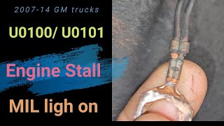
- U0100 — Lost Communication With ECM/PCM
- U0101 — Lost Communication with TCM
- U0121 — Lost Communication With Anti-Lock Brake System (ABS) Control Module
- U0140 — Lost Communication With Body Control Module (BCM)
- P0700 — Transmission Control System Malfunction (often set when the TCM loses communication)
Technical Service Bulletins (TSBs) & Recalls
- 08-07-30-021H
Platform-Specific Known Issues
- TSB #08-07-30-021H specifically calls out intermittent electrical issues and a host of communication DTCs (including U0073) caused by backed-out terminals in the transmission harness connector, chafed wiring, and corrosion in module connectors.
Mechanic-Grade Diagnostic Values
- CAN Bus Resistance — expected: ~60 Ohms. Failure: A reading of ~120 Ohms suggests an open circuit or a failed termination resistor in a module (like the ECM or EBCM). A reading near 0 Ohms indicates a short between the CAN High and CAN Low wires.
- CAN High Voltage — expected: 2.5V - 3.5V. Failure: A flatline voltage or reading outside this range indicates a bus problem (short to ground, short to power, or open).
- CAN Low Voltage — expected: 1.5V - 2.5V. Failure: A flatline voltage or reading outside this range indicates a bus problem (short to ground, short to power, or open).
Scan Tool Commands That Help
- GM Tech2 with CANdi Module: Module Status / High Speed Communication Bus — To view a list of all modules on the high-speed network and see which ones are actively communicating and which are not. This is the first step in isolating the source of the network failure. The CANdi (Controller Area Network diagnostic interface) module is required for the Tech2 to communicate with the CAN bus on these vehicles.
- GM Data Bus Diagnostic Tool: Network Diagnostics — Mentioned in TSB #08-07-30-021H as a tool available in the GM Service Information system (as of 2015) to assist in diagnosing High Speed LAN issues before proceeding with manual checks.
Wiring & Ground Locations
- GMLAN Termination Resistors — Typically, one 120-ohm resistor is internal to the Engine Control Module (ECM) and the second is internal to the Electronic Brake Control Module (EBCM).. These two resistors are at the physical ends of the network. Their combined parallel resistance creates the 60-ohm reading on a healthy bus. If one module fails or is disconnected, the bus resistance will jump to 120 ohms, causing communication errors.
- G218 — Behind the driver's side kick panel, near the A-pillar.. This is a critical ground for the Body Control Module (BCM). TSB PIT5405C notes it can become loose or have the dash insulator mat trapped underneath it, causing a poor connection and leading to various communication codes, including U0073.
- G300 — Under the vehicle, on a body mount near the driver's door.. A GM bulletin warns that undercoating from the factory or aftermarket can get between the ground eyelet and the frame, creating a poor connection that can cause intermittent communication and no-start issues.
- G102 — On the driver's side (left-hand) cylinder head or engine block.. This is a primary engine-to-chassis ground point. A loose or corroded connection here can cause unstable voltage for multiple modules, leading to network errors.
- Fuel Pump Control Module (FPCM) Connector — On the frame rail, typically near the spare tire.. The FPCM is on the high-speed CAN bus but is often overlooked. Its exposed location makes its connector and wiring vulnerable to corrosion from road salt and moisture, which can short the CAN bus and bring the entire network down.
Real Owner Repair Stories
- CorvetteForum user (2008 Chevrolet Corvette (shares GMT900-era electronics and TSBs)) — Instrument panel gauges go crazy, 'Service Traction System' message, transmission gets stuck in 2nd gear, codes U0073 and P0700 appear after 30-50 miles of driving.
❌ Tried (didn't work) The user was considering replacing the BCM or TCM, noting that others had replaced these modules multiple times.
✅ What actually fixed it The user identified TSB #08-07-30-021H and concluded the likely cause was backed-out terminals in the transmission harness connector. The user noted that the act of repeatedly unplugging the connector to swap modules could inadvertently re-seat the loose pin, leading to the misdiagnosis that a new module was the fix.
OEM Part Supersession History
15940214, 25896299, and others→22860591— Part consolidation and design updates by GM.
Heads up: Part number 22860591 fits a wide variety of GM vehicles from 2006-2013. However, it MUST be programmed with dealer-level software (Tech2/MDI) with the correct VIN and vehicle options (RPOs) to function. Installing a used BCM or a new one without programming will result in continued U0073 codes and other system malfunctions.
Model Year Variations Within This Range
- 2007-2011: The diagnostic approach for this generation is consistent and primarily covered by TSB #08-07-30-021H. This should not be confused with the 2015 and newer Yukon models, which use a different network architecture involving a Serial Data Gateway Module (SDGM) as a common failure point for U0073.
Helpful Videos

![[SOLVED] Fix Service Stabilitrack and Service Traction Control on 2007-2011 GM Trucks](https://img.youtube.com/vi/J2Lwv_T7rOY/mqdefault.jpg)
Used OEM Parts in Stock
New Aftermarket Parts Available

The information in this article is provided for general reference and educational purposes only. Vehicle specifications, procedures, and part compatibility can vary by production date, trim level, and region. Always consult your vehicle's factory service manual and verify part numbers before purchasing or performing repairs. Safety-critical components such as airbags, seat belts, and braking systems should be installed by a qualified professional.
- Gmc YUKON DENALI XL:
- 🧭 Diagnostic Flowchart
- 🎬 Helpful Videos
- 🛍️ Shop This Part
- What's Unique About the 2007-2011 Gmc YUKON DENALI XL
- Symptoms You May Notice
- Most Likely Causes
- Rare But Worth Checking
- Diagnosis Steps
- Parts You'll Likely Need
- Related Codes That Often Appear With This One
- Technical Service Bulletins (TSBs) & Recalls
- Platform-Specific Known Issues
- Mechanic-Grade Diagnostic Values
- Scan Tool Commands That Help
- Wiring & Ground Locations
- Real Owner Repair Stories
- OEM Part Supersession History
- Model Year Variations Within This Range
- 🎟️ Get 5% Off