
U0074 on 2013-2015 Cadillac ATS: Causes and Fixes for Chassis Bus Failures
U0074 on a 2013-2015 Cadillac ATS indicates a serious communication failure on the Chassis Bus. The most common cause, cited in GM Technical Service Bulletin #PIC4740E, is a poor connection at the main transmission harness connector (X1), a large, round, grey connector on the driver's side of the transmission. Inspecting, cleaning, and ensuring all pins are fully seated in this connector is the first and most crucial diagnostic step before suspecting costly module failures.
- U0074 on a 2013-2015 ATS is a critical fault on the Chassis communication bus that makes the vehicle unsafe to drive.
- Do not immediately assume a control module has failed. The most probable cause is a wiring or connector issue, specifically at the transmission X1 connector as per TSB #PIC4740E.
- Symptoms are severe and can include loss of power steering, harsh shifting, and multiple safety system warning lights.
- This is not a beginner-friendly DIY repair. Professional diagnosis is strongly recommended to accurately pinpoint the fault without replacing expensive parts unnecessarily.
What's Unique About the 2013-2015 Cadillac ATS
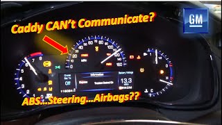
For the 2013-2015 Cadillac ATS, this code is directly addressed by manufacturer TSBs that point to specific, known weak points. TSB #PIC4740E identifies unseated pins in the transmission X1 connector as a primary cause for this and other communication codes. It also specifically calls out a potential harness chafing point on the passenger side where the transmission bell housing attaches to the engine block. Another TSB, #PIT5076E, specifically links U0074 to the 'Chassis bus' and provides a diagnostic path when it appears with other brake and steering system codes 🎬 Watch: A real-world diagnostic walkthrough of communication faults on this platform., making the diagnosis more targeted compared to a generic network fault.
Diagnostic Flowchart
Tap your situation to follow the diagnostic path that matches what you're seeing on this vehicle.
Symptoms You May Notice
- Multiple warning lights on the dashboard, especially for ABS, StabiliTrak, and Power Steering.
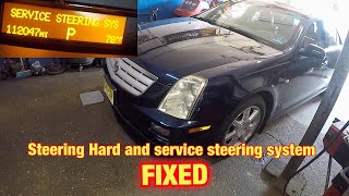
- "Service Power Steering" or "Service StabiliTrak" message on the driver information center.
- Loss of power steering assist, making the steering feel very heavy.
- Transmission may shift harshly or get stuck in one gear (Limp Mode).
- Vehicle may not crank or start.
- Scan tool may fail to communicate with the EBCM, PSCM, or TCM.
- Door locks may cycle while driving.
- Replacing the Electronic Brake Control Module (EBCM) or Power Steering Control Module (PSCM) without first thoroughly inspecting the X1 transmission connector and related wiring harness per TSB #PIC4740E. The U-code indicates a communication problem, which is far more often caused by wiring or connections than the module itself.
Most Likely Causes
- Unseated Pins or Corrosion in Transmission Connector (X1) 🔴 High Probability → Shop Transmission Assembly This is a well-documented issue identified in GM TSB #PIC4740E. The connector's location on the driver's side of the transmission makes it vulnerable to vibration, heat, and moisture, causing terminals to back out or corrode. Forum users on CadillacForums.com have repeatedly confirmed this as the primary fix for similar platforms.
How to confirm: Disconnect the large, round X1 connector at the transmission. Visually inspect for corrosion (green or white powder) on the pins and sockets. Gently tug on each individual wire on the harness side to ensure the terminal is fully seated and locked in the connector body. A side load on the wires can give a false positive lock.
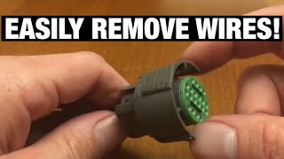
Typical fix: Clean any corroded pins with electrical contact cleaner and a small brush. Reseat any loose terminals until they click. Apply a liberal amount of dielectric grease to the connector seal before reconnecting to prevent future moisture intrusion. If terminals are damaged, a new connector pigtail may need to be spliced in. 🎬 Watch: How to remove and reseat pins in GM transmission connectors.
Est. part cost: $10-$50 - Wiring Harness Damage 🟡 Medium Probability TSB #PIC4740E specifically calls out inspecting the harness securing bracket on the passenger side where the transmission bell housing attaches to the engine block for potential chafing on ATS models. The harness can rub against this metal bracket, eventually wearing through the insulation and shorting the CAN bus wires.
How to confirm: Visually inspect the wiring harness in the area described by the TSB for any signs of rubbing, chafing, or exposed copper wires. You may need to remove heat shielding or loom to get a clear view.
Typical fix: Repair the damaged section of wire using solder and heat shrink tubing. Insulate each wire individually, then protect the bundle. Reroute or add protective conduit to the harness to prevent future damage from the bracket.
Est. part cost: $5-$25 - Failed Control Module ⚪ Low Probability Any module on the Chassis Bus (like the EBCM or PSCM) can fail internally and short out the entire network. The EBCM and PSCM are primary modules on this bus, and wiring diagrams indicate one of the 120-ohm terminating resistors may be located within the EBCM. This is less common than wiring issues but is the next logical step after wiring is confirmed perfect.
How to confirm: This is an advanced step. If wiring is confirmed good and bus resistance is incorrect (e.g., 120 ohms or 0 ohms), a technician will disconnect modules from the bus one by one. When the faulty module is disconnected, the bus resistance should return to 60 ohms and communication should be restored.
Typical fix: Replace the identified faulty module. The new module will require programming to the vehicle's VIN using dealer software (SPS).
Est. part cost: $400-$1500
Rare But Worth Checking
- Low Battery Voltage: → Shop Vehicle Battery A weak or failing battery can cause system voltage to drop during cranking, leading to various control modules temporarily dropping offline and generating false network codes. Always ensure the battery is fully charged (above 12.4V) and the charging system is working correctly before diagnosing network faults.
- Poorly Installed Aftermarket Electronics: Improperly installed remote starters, alarms, or audio systems that are tapped into the vehicle's data network can disrupt communication and cause a U0074 code. These devices can introduce noise or improper resistance to the bus.
Diagnosis Steps
- Verify battery health and charging system operation. Ensure voltage is stable and above 12.4V with the engine off.
- Connect a professional scan tool to read all codes from all modules. Note which modules are not communicating (e.g., EBCM, PSCM).
- Follow the instructions in TSB #PIC4740E: Disconnect the transmission X1 connector. Inspect thoroughly for loose pins, corrosion, or damage. Gently tug each wire to confirm it is seated.
- Inspect the wiring harness for chafing, especially near the securing bracket on the passenger side of the transmission bell housing, as noted in TSB #PIC4740E for the ATS.
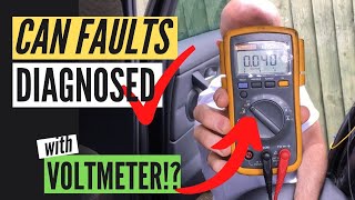
- If wiring and connectors are good, measure the resistance of the Chassis Bus at the OBD-II port. With the battery disconnected, measure resistance between the appropriate pins (e.g., Pin 12 and Pin 13 for Chassis Bus, or Pin 6 and Pin 14 for High-Speed CAN). A healthy network should read approximately 60 ohms. 🎬 See how to properly test CAN bus resistance with a multimeter.
- If resistance is 120 ohms, it indicates an open circuit or a faulty/disconnected terminating resistor. If resistance is near 0 ohms, there is a short between the two CAN wires.
- If the cause is still not found, begin disconnecting modules on the Chassis Bus one at a time (e.g., EBCM, PSCM) and re-checking for communication restoration. When communication returns, the last module disconnected is likely the source of the fault.
Parts You'll Likely Need
- Transmission Connector Pigtail
(OEM #GM 13584094 (ACDelco PT2712))— If the transmission X1 connector or its terminals are damaged by corrosion or heat beyond cleaning, a new pigtail must be spliced into the harness. This part is a common multi-purpose connector used by GM.
Trusted brands: ACDelco (Genuine GM)
OEM price range: $30-$60
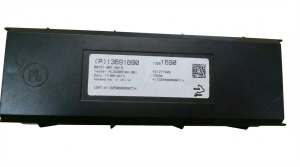
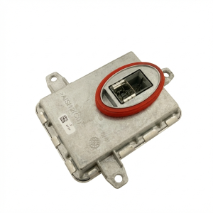
Aftermarket price range: $20-$40 - Electronic Brake Control Module (EBCM)
(OEM #22934560, 23156303 (Varies by RWD/AWD and options, verify with VIN))— If diagnosed as the source of the network failure, the EBCM must be replaced. It is one of the two terminating resistors for the Chassis Bus and a critical safety component.
Trusted brands: ACDelco
OEM price range: $700-$1500
Aftermarket price range: $400-$900
Related Codes That Often Appear With This One
- U0121 — Stands for 'Lost Communication With Anti-Lock Brake System (ABS) Control Module'. This is a direct symptom of U0074, as the ABS module (EBCM) is a primary module on the affected Chassis Bus.
- U0101 — Stands for 'Lost Communication With TCM'. This often appears because the transmission connector (X1) is the source of the fault, disrupting communication from the Transmission Control Module.
- U0100 — Stands for 'Lost Communication With ECM/PCM'. This can be set when the network failure is severe enough to affect communication with the Engine Control Module.
- C0561 — Stands for 'System Disabled Information Stored'. This is a generic code set by the EBCM to indicate that the StabiliTrak system has been disabled, often due to a communication loss like U0074.
Technical Service Bulletins (TSBs) & Recalls
- PIC4740E: No Crank, Multiple Warning Telltales On, Trans Shifts Hard
- PIT5076E: Service Stability Message, DTC C0710 71 and/or Chassis Buss Communication DTCs
Platform-Specific Known Issues
- TSB #PIC4740E: Explicitly mentions that on the 2013-2015 ATS, conditions like no-start, harsh shifting, and multiple warning lights accompanied by code U0074 can be caused by unseated pins in the transmission X1 connector. It also directs technicians to check for harness chafing at a specific bracket near the bell housing.
- TSB #PIT5076E: Instructs technicians that if U0074 is set with other specific chassis codes (like C0186, C0196, C0287) and will not clear, the Chassis Bus itself must be diagnosed. It also notes that in some cases, a faulty MDI (the diagnostic interface tool) could be the cause.
Mechanic-Grade Diagnostic Values
- Chassis CAN Bus Resistance — expected: ~60 Ω (measured between bus high/low pins at DLC with battery disconnected). Failure: A reading of ~120 Ω indicates an open circuit or an offline terminating resistor. A reading near 0 Ω indicates a short between the two CAN wires.
- CAN Bus Voltage — expected: CAN High: ~2.5-3.5V; CAN Low: ~1.5-2.5V (key on, engine off). The two signals should be a near mirror-image of each other centered around 2.5V when viewed on an oscilloscope.. Failure: A flat line, or voltage stuck high or low on either wire indicates a short to power or ground.
- CAN Bus Short to Ground Check — expected: OL (Open Line / infinite resistance) between each CAN bus pin and a known good chassis ground (e.g., DLC pin 4 or 5).. Failure: Any continuity or low resistance reading indicates a short to ground on that CAN line.
Hidden / Shadow Codes Worth Checking
- U0074 00: The '00' is a GM-specific symptom byte that often accompanies the main DTC. It typically indicates a general 'Bus Off' status or a 'rationality check' failure, confirming the module has commanded the bus to shut down due to excessive errors. (see via A professional scan tool capable of reading manufacturer-specific codes, such as the GM GDS2.)
Scan Tool Commands That Help
- GM GDS2 (Global Diagnostic System 2): Vehicle DTC Information / All DTC Check — This is the initial step to see which modules are reporting codes and, more importantly, which modules are not communicating at all.
- GM GDS2 (Global Diagnostic System 2): Module Diagnostics > [Module Name] > Control Functions — After identifying non-communicating modules (like EBCM or PSCM), a technician can use this function on a *communicating* module on the same bus to see if the bus itself is partially active. For example, commanding lights on/off via the BCM can help verify network integrity elsewhere.
- GM GDS2 (Global Diagnostic System 2): Configuration/Reset Functions — This is required after replacing a control module (like the EBCM or PSCM) to program it to the vehicle's VIN and configure its specific options.
Wiring & Ground Locations
- Chassis Bus Terminating Resistors — There are two 120 Ω resistors. One is typically internal to the EBCM. A wiring diagram for a 2014 ATS also shows a 'High speed bus terminating resistor' located separately in the harness, forward of the right rear lamp assembly.. The entire CAN bus requires exactly two 120 Ω resistors to function. If one is disconnected or fails, bus resistance will read 120 Ω instead of 60 Ω, causing communication to fail.
- G101 — Engine compartment, located above the left (driver's side) headlight assembly.. Wiring diagrams indicate that both the Electronic Brake Control Module (EBCM) and the Power Steering Control Module (PSCM) share this ground point. A loose or corroded G101 can create a ground potential difference between these two critical modules on the Chassis Bus, leading to communication errors like U0074.
- X1 Connector — The main 16-pin electrical connector on the driver's side of the transmission assembly.. This is the primary suspect identified in TSB #PIC4740E. It carries data lines for multiple modules, and loose or corroded pins here are the most common cause of the U0074 code on this platform.
Real Owner Repair Stories
- ? ()
Helpful Videos
Used OEM Parts in Stock
New Aftermarket Parts Available


The information in this article is provided for general reference and educational purposes only. Vehicle specifications, procedures, and part compatibility can vary by production date, trim level, and region. Always consult your vehicle's factory service manual and verify part numbers before purchasing or performing repairs. Safety-critical components such as airbags, seat belts, and braking systems should be installed by a qualified professional.
- Cadillac ATS:
- 🧭 Diagnostic Flowchart
- 🎬 Helpful Videos
- 🛍️ Shop This Part
- What's Unique About the 2013-2015 Cadillac ATS
- Symptoms You May Notice
- Most Likely Causes
- Rare But Worth Checking
- Diagnosis Steps
- Parts You'll Likely Need
- Related Codes That Often Appear With This One
- Technical Service Bulletins (TSBs) & Recalls
- Platform-Specific Known Issues
- Mechanic-Grade Diagnostic Values
- Hidden / Shadow Codes Worth Checking
- Scan Tool Commands That Help
- Wiring & Ground Locations
- Real Owner Repair Stories
- 🎟️ Get 5% Off