
U0074 on 2013-2015 Cadillac XTS: Chassis Bus Communication Failure Guide
U0074 on a 2013-2015 Cadillac XTS indicates a serious communication failure on the chassis data network. This is often caused by a wiring issue, a faulty Electronic Brake Control Module (EBCM), or a bad Power Steering Control Module (PSCM). Do not drive the vehicle, as critical systems like power steering and ABS may be disabled. Professional diagnosis is strongly recommended due to the complexity of network issues.
- U0074 on a 2013-2015 Cadillac XTS is a critical network failure code, not a simple sensor fault.
- Do not drive the vehicle, as power steering, ABS, and stability control may be inoperative.
- The problem is most often a wiring/connector issue or a single failed module taking down the entire chassis network.
- This code will almost always appear with a long list of other 'U' and 'C' codes; they should be diagnosed together as a single network fault.
- Due to the complexity, professional diagnosis with advanced tools is strongly recommended to avoid costly misdiagnosis.
What's Unique About the 2013-2015 Cadillac XTS
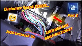
On the Cadillac XTS and related GM Epsilon II platforms like the Buick LaCrosse, the U0074 code is rarely an isolated fault. It's a strong indicator of a network-wide problem on the chassis bus, as documented in GM Technical Service Bulletin #PIT5076E. This bulletin notes that U0074 often appears with a cluster of other communication and chassis system codes, directing technicians to diagnose the entire bus rather than focusing on a single module that may just be reporting the error. On these platforms, the EBCM is a common point of failure that can cause this code.
Diagnostic Flowchart
Tap your situation to follow the diagnostic path that matches what you're seeing on this vehicle.
Symptoms You May Notice
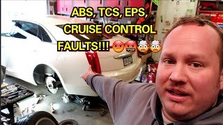
- Multiple warning lights on the dashboard, including ABS, Traction Control, and StabiliTrak
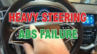
- "Service Power Steering" message displayed
- Loss of power steering assist, making the wheel hard to turn
- Cruise control becomes inoperative
- Hard shifting from the transmission
- Vehicle may not start or crank
- Instrument cluster may go blank or fail to operate intermittently
- Replacing a single module (like the power steering rack or ABS pump) just because its warning light is on. The module is often just reporting the network failure, not causing it. 🎬 See why replacing parts without testing can make things worse
- Overlooking a simple wiring or connector issue and unnecessarily replacing an expensive control module. A thorough inspection of known problem areas like the EBCM and transmission connectors is critical.
Most Likely Causes
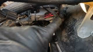
- Wiring Harness or Connector Issue 🔴 High Probability GM has identified issues with unseated pins and corrosion in major harness connectors on related platforms. TSB PIC4740F points to the transmission connector (X1) as a common trouble spot. The wiring harness leading to the EBCM, located under the coolant reservoir, is also susceptible to heat damage and chafing.
How to confirm: Visually inspect all major connectors on the chassis bus, especially the main connector at the EBCM and the transmission (X1). Check for corrosion, backed-out pins, or physical damage to the harness. A technician can perform a 'drag test' on the female connector pins to check for proper tension. Tug gently on each wire at the connector to ensure it's fully seated.
Typical fix: Repairing the damaged section of the wiring harness or cleaning and reseating the affected connector. This may involve replacing terminals or the connector housing itself. Applying dielectric grease during reassembly can prevent future corrosion.
Est. part cost: $10-$100 - Failed Control Module 🟡 Medium Probability Any module on the chassis bus (e.g., EBCM, PSCM, or a rear radar sensor) can fail internally and broadcast disruptive signals (known as 'babbling') or short the bus, causing the entire network to shut down. The EBCM is a frequently reported failure point, sometimes due to an intermittent internal fault.
How to confirm: This requires a process of elimination. A technician will disconnect modules from the chassis bus one by one while monitoring bus health with a scan tool. When the faulty module is disconnected, communication among the remaining modules will be restored. Advanced diagnosis with an oscilloscope can show the voltage from a module dropping out when it's tapped, confirming an internal fault.
Typical fix: Replace the faulty control module. The new module will almost always require programming by a dealer or qualified shop to work with the vehicle. 🎬 Watch: How to program a replacement ABS module
Est. part cost: $400-$1500 - Failed CAN Bus Terminating Resistor ⚪ Low Probability → Shop Data Link Resistor
How to confirm: The CAN bus has two 120-ohm terminating resistors. A technician can measure the resistance between the CAN High (Pin 6) and CAN Low (Pin 14) wires at the OBD-II port with the battery disconnected. A healthy bus will read approximately 60 ohms. A reading of 120 ohms indicates an open circuit or a problem with one of the resistors.
Typical fix: The terminating resistors are typically located inside a control module (often the EBCM and another module like the airbag module). If a resistor fails, the entire module must be replaced.
Est. part cost: $500-$1200
Rare But Worth Checking
- Poor Ground Connection: A corroded or loose ground for one of the main control modules can introduce electrical noise and cause communication faults. Key interior ground points to check are G201/G301 (driver's kick panel) and G300 (passenger's kick panel).
- Aftermarket Electronics: Improperly installed aftermarket devices (like remote starters or alarms) spliced into the vehicle's data network are a common source of communication errors.
- Faulty Diagnostic Cable: As noted in TSB PIT5076C, a faulty MDI (Multiple Diagnostic Interface) cable connecting the scan tool to the vehicle can itself induce communication errors that mimic a real fault. Trying a different cable can rule this out.
Diagnosis Steps
- Connect a professional scan tool capable of reading all vehicle modules, not just the engine computer. Record all stored DTCs from all modules.
- Check for relevant TSBs, such as #PIT5076E and #PIC4740F, which directly address this code and its companions.
- With the battery disconnected, measure the resistance between Pin 6 (CAN High) and Pin 14 (CAN Low) at the OBD-II port. The reading should be approximately 60 ohms. A reading of 120 ohms indicates an open in the bus; near 0 ohms indicates a short.
- Visually inspect the main chassis wiring harness and all connectors for modules on the affected bus. Pay close attention to connectors at the EBCM (under the coolant reservoir), transmission (X1 connector), and any other non-communicating modules.
- Inspect major ground points, particularly those in the driver and passenger kick panels (G301, G300) and engine bay (G100, G101).
- If wiring appears intact, begin disconnecting modules from the chassis bus one at a time. After disconnecting each module, re-check bus communication. If communication is restored after unplugging a specific module, that module is the source of the fault.
- For advanced diagnosis, use an oscilloscope to view the CAN bus waveform. A healthy bus will show a clean, square wave. A distorted signal points to wiring issues or a module that is broadcasting corrupted data. This can also be used to verify power and ground signals at the modules.
Parts You'll Likely Need
- Electronic Brake Control Module (EBCM)
(OEM #22997125)— The EBCM is a primary node on the chassis bus and a common point of failure that can bring down the network. It often contains a terminating resistor and can suffer from internal faults.
Trusted brands: ACDelco (GM Genuine)
OEM price range: $575-$1200
Aftermarket price range: $400-$800 - Power Steering Control Module (PSCM)
(OEM #22928962)— As another critical module on the chassis bus, an internal failure in the PSCM can cause a U0074 code. This part number is superseded; always verify with VIN.
Trusted brands: ACDelco (GM Genuine)
OEM price range: $220-$500
Aftermarket price range: $200-$400 - Wiring Harness Repair Supplies — If the cause is a broken wire or corroded connector, which is a high-probability cause, only repair materials like terminals, connector pigtails, or wiring are needed.
Trusted brands: ACDelco
OEM price range: $20-$100
Aftermarket price range: $10-$50
Related Codes That Often Appear With This One
- U0121 — Lost Communication With Anti-Lock Brake System (ABS) Control Module
- U0125 — Lost Communication With Yaw Rate Sensor Module
- U0126 — Lost Communication With Steering Angle Sensor Module
- U0131 — Lost Communication With Power Steering Control Module
- C0186, C0196, C0287 — These are chassis codes related to the brake and stability systems that are set when communication is lost.
- U0100, U0101, U0140 — These codes indicate lost communication with the ECM, TCM, and BCM respectively, and can appear if the bus failure is widespread.
Technical Service Bulletins (TSBs) & Recalls
- PIT5076E: Mentions that U0074 can set along with numerous other codes, pointing to a fault on the Chassis bus that needs diagnosis. Also notes that a faulty MDI diagnostic cable can sometimes be the cause.
- PIC4740F: While not specific to the XTS, this TSB for other Cadillacs (ATS, CTS, SRX) highlights a known issue with unseated pins in the transmission harness connector (X1) causing a loss of communication, which is a relevant and valuable check.
Platform-Specific Known Issues
- TSB PIT5076E - Widespread Chassis Bus Fault: Per TSB #PIT5076E, this code is frequently seen with other communication codes (U0077, U0125, U0126, etc.) and chassis codes (C0186, C0196, etc.), indicating a general fault on the Chassis bus that requires comprehensive network diagnosis, not just replacement of one part.
- TSB PIC4740F - Transmission Connector Inspection: → Shop Transmission Assembly A critical TSB for related platforms points to unseated pins in the X1 transmission harness connector as a primary cause for U0074 and other communication failures. A 'tug test' on these wires is a required first step before module replacement.
Mechanic-Grade Diagnostic Values
- CAN Bus Network Resistance — expected: ~60 Ohms. Failure: 120 Ohms indicates an open circuit or missing terminating resistor. ~0 Ohms indicates a short between CAN High and Low wires.
- CAN Bus Voltage (Key On, Engine Off) — expected: CAN High (Pin 6 to ground): ~2.6V. CAN Low (Pin 14 to ground): ~2.4V.. Failure: Voltages that are stuck high (near 5V), low (near 0V), or are identical on both lines indicate a bus fault.
- Module Ground Connection Voltage Drop — expected: Less than 0.1 Volts. Failure: A reading higher than 0.1V indicates excessive resistance in the ground circuit, which can cause communication errors.
Scan Tool Commands That Help
- GDS2 (GM Global Diagnostic System 2): Module Diagnostics / Data Display — To view a list of all control modules on the network and see which ones are not communicating. This is the primary screen used when performing the module isolation test (disconnecting modules one-by-one) to see when communication is restored.
- GDS2 (GM Global Diagnostic System 2): Configure and Reset Functions — After replacing a control module such as the EBCM or PSCM, this function is used to program the new module with the vehicle's VIN and specific configuration, a necessary step for it to operate correctly.
Wiring & Ground Locations
- X1 Connector — The main 16-pin electrical connector on the side of the transmission case.. TSB PIC4740F identifies unseated pins or corrosion in this specific connector as a high-probability cause for U0074 and a host of other communication codes.
- EBCM Connector — At the Electronic Brake Control Module, typically located under or near the coolant reservoir in the engine bay.. This is a major hub for the chassis bus. The harness here is prone to chafing and heat damage, and the connector pins can corrode, causing a network failure. It is a 38-way sealed connector.
- G100 / G101 — Main engine compartment grounds. G100 is often on the left front of the engine compartment, while G101 is on the left radiator support.. A poor engine bay ground can create a voltage differential between critical modules like the ECM and EBCM, leading to communication faults.
- G301 — Located in the cabin, behind the driver's side kick panel.. This is a key interior ground point for several modules. Corrosion or looseness here can cause intermittent communication issues that are hard to trace.
Real Owner Repair Stories
- CadillacForums user report (2008 Cadillac CTS (platform-mate)) — Multiple 'U' codes including U0073, U0100, U0101, U0121, U0140. No communication with multiple modules.
❌ Tried (didn't work) Replacing the Transmission Control Module (TCM)
✅ What actually fixed it The problem was a corroded pin inside one of the main harness connectors at the Engine Control Module (ECM). Cleaning the corrosion from the ECM connector and pin resolved all communication issues.
When the Usual Fixes Don't Work
- In a documented repair on a similar platform, a vehicle presented with a host of communication codes, including U0121 and U0101. The owner first replaced the Transmission Control Module (TCM), believing it to be the fault, but this did not resolve the issue. Further diagnosis revealed the true cause was a single corroded pin in a connector at the Engine Control Module (ECM). This serves as strong evidence against replacing the first module that flags a code, reinforcing the need for a full network and wiring diagnosis first.
OEM Part Supersession History
22928962→84024543— Part has been updated by the manufacturer.
Heads up: This is the Power Steering Control Module (PSCM). The replacement part requires programming with a tool like GDS2 to function in the vehicle.22997125→N/A— This EBCM part number appears current, but repair services are common.
Heads up: Due to cost or availability, many owners opt to send their original EBCM for repair rather than buying new. A repaired module typically does not require reprogramming. A new or used replacement module will require programming.
Helpful Videos
We Have This Part in Stock

The information in this article is provided for general reference and educational purposes only. Vehicle specifications, procedures, and part compatibility can vary by production date, trim level, and region. Always consult your vehicle's factory service manual and verify part numbers before purchasing or performing repairs. Safety-critical components such as airbags, seat belts, and braking systems should be installed by a qualified professional.
- Cadillac XTS:
- 🧭 Diagnostic Flowchart
- 🎬 Helpful Videos
- 🛍️ Shop This Part
- What's Unique About the 2013-2015 Cadillac XTS
- Symptoms You May Notice
- Most Likely Causes
- Rare But Worth Checking
- Diagnosis Steps
- Parts You'll Likely Need
- Related Codes That Often Appear With This One
- Technical Service Bulletins (TSBs) & Recalls
- Platform-Specific Known Issues
- Mechanic-Grade Diagnostic Values
- Scan Tool Commands That Help
- Wiring & Ground Locations
- Real Owner Repair Stories
- When the Usual Fixes Don't Work
- OEM Part Supersession History
- 🎟️ Get 5% Off