
U0074 on 2015-2018 GMC Yukon XL: Causes and Fixes for Communication Bus Failure
U0074 on a 2015-2018 GMC Yukon XL indicates a serious communication failure on the chassis network. This often triggers multiple warning lights like 'Service StabiliTrak' and 'Service Power Steering'. The cause is frequently a wiring or connector issue, not a failed module. Common problem areas include chafed wiring harnesses in the engine bay and corroded ground connections. Professional diagnosis is strongly recommended.
- U0074 is a critical fault that makes the vehicle unsafe to drive. Address it immediately.
- Multiple warning lights ('Service StabiliTrak', 'Service Power Steering', ABS) are the primary symptom.
- The problem is most often found in the wiring or connectors of the chassis CAN bus, not the expensive modules themselves.
- This is not a DIY-friendly repair. Accurate diagnosis requires professional tools and expertise to avoid costly misdiagnosis.
- Always check for relevant TSBs, as GM has provided specific diagnostic guidance for this code on your vehicle.
What's Unique About the 2015-2018 Gmc YUKON XL
For the 2015-2018 K2XX platform Yukon XL, the chassis CAN bus is integral to safety systems like StabiliTrak, ABS, and electric power steering. A failure here is not a minor glitch; it can immediately compromise vehicle control. GM has issued technical service bulletins (TSBs) that specifically address communication issues on this bus, often pointing technicians to diagnose the network itself before replacing expensive modules. For instance, TSB PIP5427B notes that U0074 should be diagnosed before other related codes like P2635 because the communication fault is the root cause. Another TSB, 18-NA-161, points to high resistance in battery jumper cables or ground cables as a potential cause for a host of communication issues, including those that trigger a U0074. Furthermore, TSBs like #20-NA-214 detail specific engine harness chafing points near the ECM/TCM bracket, upper control arm, and shock tower that can lead to this code.
Diagnostic Flowchart
Tap your situation to follow the diagnostic path that matches what you're seeing on this vehicle.
Symptoms You May Notice
- "Service StabiliTrak" message on the driver information center (DIC)
- "Service Power Steering" message on the DIC
- ABS and Traction Control warning lights illuminated
- Check Engine Light illuminated
- Loss of power steering assist, making steering very difficult
- Vehicle may stall or fail to start
- Instrument cluster may display blank or frozen screens or sweep gauges on startup
- Transmission may shift erratically or not at all
- Radio or HVAC displays may go blank
- Replacing the Electronic Brake Control Module (EBCM) or Power Steering Control Module (PSCM) without first thoroughly testing the CAN bus wiring and grounds. The fault is often in the wiring, not the module itself.
- Replacing the fuel pump or FPCM for a P2635 code without first diagnosing the U0074, as the communication loss is the root cause.
Most Likely Causes
- Damaged or Chafed Wiring Harness 🔴 High Probability GM has identified several specific points where the engine wiring harness can chafe against chassis components. TSB #20-NA-214 points to contact with the ECM/TCM bracket, the driver's side upper control arm, and the shock tower bolt. Vibration and engine roll cause the harness to rub through, eventually shorting the CAN bus wires within the loom.
How to confirm: A technician will perform a visual inspection of the harness in the areas mentioned in TSBs, which often requires removing the driver's side front wheel and wheelhouse liner for access. They will also use a multimeter to check for continuity and resistance on the CAN bus wires at the OBD-II port (should be ~60 ohms) and at module connectors.
Typical fix: Repairing the damaged section of wire by soldering and sealing with heat shrink. The harness is then rerouted or protected with anti-abrasion tape and secured with zip ties to prevent future contact.
Est. part cost: $10-$100 - Faulty Control Module 🟡 Medium Probability Any module on the chassis CAN bus can fail internally. When it does, it can short out the entire network, preventing other modules from communicating. The Electronic Brake Control Module (EBCM) and Power Steering Control Module (PSCM) are common culprits.
How to confirm: A technician will use a scan tool to see which modules are offline. They will then disconnect modules one by one from the network. If communication is restored after unplugging a specific module, that module is identified as the source of the problem.
Typical fix: Replacement of the faulty module. The new module will require programming to the vehicle's VIN using a tool like TIS2WEB.
Est. part cost: $400-$1200 - Poor Ground Connection 🟡 Medium Probability Vehicle control modules rely on clean, solid ground connections. TSB 18-NA-161 specifically highlights issues with high resistance in the short ground cables between the battery and the chassis, which can cause a wide range of communication DTCs. Ground packs, such as those on the frame rail, can also become corroded or loose.
How to confirm: Locate and inspect the main ground points for the chassis and engine bay (e.g., G104 on the back of the cylinder head, G400 on the rear frame). Check for tightness and corrosion. A voltage drop test on the ground circuit is the definitive method to confirm its integrity.
Typical fix: Cleaning the ground connection point down to bare metal and re-securing the ground strap or wire. In some cases, the short ground cable itself must be replaced.
Est. part cost: $5-$50
Rare But Worth Checking
- Aftermarket Accessories: Improperly installed aftermarket equipment (like remote starters, alarms, or trailer brake controllers) spliced into the vehicle's data network can disrupt communication and cause a U0074 code.
- Faulty Aftermarket Fuel Pump Control Module (FPCM): → Shop Fuel Pump GM has noted in TSB #PIE0493 that some aftermarket FPCMs may contain an incorrect terminating resistor, which can disrupt the entire high-speed data bus and cause communication codes.
- PSCM Calibration Error: TSB 20-NA-100 describes a calibration error in the Power Steering Control Module (PSCM) that can cause various communication DTCs to remain current even after the initial fault is gone. The fix is to reprogram the PSCM with the latest software.
Diagnosis Steps
- Connect a professional scan tool and attempt to communicate with all modules. Note which modules are not responding.
- Check for any Technical Service Bulletins (TSBs) related to U0074. TSBs PIP5427B, PIT5076E, 20-NA-214, and 18-NA-161 are highly relevant.
- Perform a thorough visual inspection of the engine wiring harness, specifically focusing on the chafe points identified in TSBs: near the ECM/TCM bracket, upper control arm, and shock tower.
- Inspect ground connections, particularly the battery ground cable and chassis grounds, for corrosion and tightness.
- With the ignition off, measure the resistance between pins 6 (CAN High) and 14 (CAN Low) at the OBD-II port. A healthy network should read approximately 60 ohms. A reading of 120 ohms indicates an open circuit or a missing terminating resistor, while a reading near 0 ohms indicates a short circuit.
- If the resistance is incorrect, begin disconnecting modules on the chassis bus one at a time (starting with the EBCM and PSCM) and re-checking the resistance to isolate the faulty circuit or module.
- If wiring appears intact, use an oscilloscope to view the CAN bus signals at the OBD-II port. Look for clean, square waves. A distorted or mirrored signal points to a network problem.
- Check power and ground connections at the non-communicating modules to rule out a simple power supply issue.
Parts You'll Likely Need
- Electronic Brake Control Module (EBCM)
(OEM #84527648, 84176782 (ACDelco))— The EBCM is a key module on the chassis bus and contains one of the network's terminating resistors. An internal failure can take down the entire bus. It should only be replaced after confirming it is the source of the failure through isolation testing.
Trusted brands: ACDelco
OEM price range: $500-$900
Aftermarket price range: $300-$600 - Power Steering Control Module (PSCM)
(OEM #844447)— The PSCM is another critical node on the chassis bus. A failure within this module can short the network, causing a U0074. It must be isolated and confirmed as the fault before replacement.
Trusted brands: ACDelco
OEM price range: $350-$600
Aftermarket price range: $250-$450
Related Codes That Often Appear With This One
- P2635 — This code relates to the fuel pump flow performance. TSB PIP5427B states that a U0074 communication loss between the ECM and Fuel Pump Control Module can cause P2635. The U0074 code must be diagnosed first.
- U18A2 — This is another communication code. TSB PIP5427B specifies that if both U0074 and U18A2 are present, U0074 takes diagnostic priority.
- U0100, U0101, U0121, U0131, U0140 — These codes indicate a loss of communication with the ECM, TCM, EBCM, PSCM, and BCM respectively. Their presence alongside U0074 confirms a wider network failure and are often linked to wiring harness chafing issues described in TSB #20-NA-214.
- C0186, C0196, C0287 — These are chassis-related codes often seen with U0074. TSB PIT5076E groups them together and points to a fault on the chassis bus as the likely cause.
Technical Service Bulletins (TSBs) & Recalls
- PIP5427B: Advises that U0074 takes diagnostic priority over codes like P2635 and U18A2, as the communication loss is the root cause.
- PIT5076E: Recommends diagnosing the chassis bus when U0074 appears with other chassis codes like C0186, C0196, etc.
Platform-Specific Known Issues
- Engine Harness Chafing: The K2XX platform has documented issues with the engine wiring harness rubbing against the ECM/TCM bracket, the upper control arm, and the shock tower bolt. This is a primary cause of U0074 and is detailed in GM TSB #20-NA-214. The repair involves fixing the damaged wires and securing the harness away from these contact points.
- High-Resistance Ground Cables: GM TSB 18-NA-161 addresses a problem where the short jumper cables between the battery posts and the main junction block, or the main negative battery cable, can develop high internal resistance. This causes voltage drops that lead to a cascade of communication codes, including U0074, and symptoms like 'Service Power Steering'.
Mechanic-Grade Diagnostic Values
- CAN Bus Resistance (Chassis Bus) — expected: ~60 Ω. Failure: A reading of ~120 Ω indicates an open circuit or one of the two terminating resistors is offline. A reading near 0 Ω indicates a short between the CAN high and low wires.
- CAN High Voltage (Oscilloscope) — expected: Signal toggles between ~2.5V (recessive) and ~3.5V (dominant).. Failure: A flat line, voltage stuck high (~9V or more), or a distorted waveform indicates a bus fault.
- CAN Low Voltage (Oscilloscope) — expected: Signal mirrors CAN High, toggling between ~2.5V (recessive) and ~1.5V (dominant).. Failure: A flat line, voltage stuck high (~9V or more), or a distorted waveform indicates a bus fault.
- Communication Enable Circuit (Circuit 5986) Voltage — expected: Approximately 12V when the BCM is awake (e.g., ignition ON).. Failure: Low or no voltage prevents modules on the chassis bus from waking up and communicating, even if the CAN wiring is intact.
Scan Tool Commands That Help
- GDS2 (GM Global Diagnostic System 2): Vehicle DTC Information / All DTC Check — This is the first step to see a complete list of which modules are reporting codes and, more importantly, which modules are not communicating at all.
- GDS2 (GM Global Diagnostic System 2): Module Diagnostics > [Module Name] > Control Functions — After identifying which modules are offline, this function can be used to test the functionality of the *remaining* online modules. This helps verify the integrity of the rest of the network and can help isolate the fault by confirming which systems are still working properly.
Wiring & Ground Locations
- Chassis Bus @ DLC — Pins 12 (CAN High, Tan/Black wire) and 13 (CAN Low, Tan wire) on the vehicle's OBD-II Data Link Connector (DLC) under the driver's side dashboard.. This is the primary access point for testing the resistance and voltage of the entire Chassis CAN bus network with a multimeter or oscilloscope.
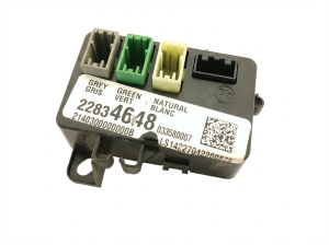
- Terminating Resistors — The network has two 120-ohm resistors. One is internal to the Engine Control Module (ECM). The second can be internal to the Electronic Brake Control Module (EBCM) or Airbag Module (SDM), OR it may be an external resistor taped to the wiring harness, often near the spare tire and Fuel Pump Control Module.. The network requires both resistors to function. A reading of 120 ohms instead of 60 ohms at the DLC indicates one is missing or offline. Knowing the possible locations is critical for diagnosis.
- G218 — A critical body ground located on the driver's side A-pillar, behind the plastic kick panel and under the dash.. This is a primary ground for the Body Control Module (BCM). A poor connection here (often due to sound-deadening material trapped under the terminal from the factory) can cause a host of communication codes.
- Circuit 5986 (Communication Enable) — A wire that runs from the BCM to multiple modules on the chassis bus. It is commonly routed in the harness under the driver's and passenger's side door sill plates.. This circuit provides a 12V 'wake-up' signal. A break or short in this wire will prevent modules from communicating, mimicking a CAN bus failure. TSB PIT5457D identifies this as a known issue.
- Splice J365 — Located in the wiring harness under the passenger's front door sill plate.. This is a known splice point for the critical Circuit 5986 (Communication Enable). Corrosion or a bad connection here can take down multiple modules.
Real Owner Repair Stories
- Global Commerce CA YouTube Channel (2023 Chevy Silverado (newer K2XX platform, but same diagnostic principle)) — U0074, U0103, no communication with multiple modules, radio and backup camera not working.
❌ Tried (didn't work) Clearing codes
✅ What actually fixed it The technician found a large electrical connector under the passenger seat was not fully seated. After unplugging and firmly re-seating the connector, all communication was restored and all codes cleared. - Chevy Tahoe / GMC Yukon Forum user experience (General GM SUV) — Multiple 'U' codes, vehicle won't start, CAN bus network down.
❌ Tried (didn't work) Initial visual inspection
✅ What actually fixed it The problem was a faulty seat heater control module that was shorting out the data bus. The fix was found by disconnecting modules one by one from the network. When the faulty module was unplugged, the rest of the network came back online and the vehicle started.
"I Checked Everything" — The Actual Cause
- The electrical equivalent is when a visual inspection or basic continuity test passes, but a fault still exists. GM TSB PIT5171B notes that CAN bus wires can break *internally* within the insulation, showing no external signs of damage like chafing or cuts. A simple continuity check with a multimeter might even pass if the copper strands are barely touching. The definitive test is to gently pull on the wire in the suspected area; if the insulation stretches, it indicates the conductor inside is broken.
Model Year Variations Within This Range
- 2015-2020 (K2XX Platform): The location of the second 120-ohm terminating resistor can vary. On some trucks, it is an external, replaceable resistor (a small gray connector) taped to the rear chassis harness, often near the spare tire and Fuel Pump Control Module. On other configurations, this resistor is located internally within a module, most commonly the Electronic Brake Control Module (EBCM) or the Inflatable Restraint Sensing and Diagnostic Module (Airbag Module). This is a critical diagnostic difference, as a technician may waste time looking for an external resistor that does not exist on a particular vehicle.
We Have This Part in Stock

The information in this article is provided for general reference and educational purposes only. Vehicle specifications, procedures, and part compatibility can vary by production date, trim level, and region. Always consult your vehicle's factory service manual and verify part numbers before purchasing or performing repairs. Safety-critical components such as airbags, seat belts, and braking systems should be installed by a qualified professional.
- Gmc YUKON XL:
- 🧭 Diagnostic Flowchart
- 🛍️ Shop This Part
- What's Unique About the 2015-2018 Gmc YUKON XL
- Symptoms You May Notice
- Most Likely Causes
- Rare But Worth Checking
- Diagnosis Steps
- Parts You'll Likely Need
- Related Codes That Often Appear With This One
- Technical Service Bulletins (TSBs) & Recalls
- Platform-Specific Known Issues
- Mechanic-Grade Diagnostic Values
- Scan Tool Commands That Help
- Wiring & Ground Locations
- Real Owner Repair Stories
- "I Checked Everything" — The Actual Cause
- Model Year Variations Within This Range
- 🎟️ Get 5% Off