
U0077 on 2010-2015 Buick LaCrosse: Chassis Bus Communication Failure Causes and Fixes
Code U0077 on a 2010-2015 Buick LaCrosse means there's a communication failure on the Chassis CAN Bus. This often points to a wiring problem (chafing, corrosion), particularly under the driver's or passenger's sill plates, or a faulty module like the Electronic Brake Control Module (EBCM). Diagnosis is complex and usually requires professional tools to isolate the fault on the network.
- U0077 is a serious network communication code, not a simple sensor failure.
- Do not drive the vehicle, as safety systems like ABS, traction control, and power steering may be disabled.
- The most likely causes are wiring damage or a faulty control module on the chassis network.
- Always diagnose the wiring harness and connections thoroughly before spending money on expensive modules like the EBCM or PSCM.
- This is a complex issue that almost always requires professional diagnosis with advanced tools.
What's Unique About the 2010-2015 Buick LACROSSE
For this generation of LaCrosse, built on the GM Epsilon II platform, the Chassis CAN bus connects critical safety systems, including the Electronic Brake Control Module (EBCM) and the Power Steering Control Module (PSCM). A GM Technical Service Bulletin (TSB) specifically links U0077 to communication breakdowns with these modules, often accompanied by 'Service Power Steering' or 'Service Stability' messages on the dash. A separate TSB, PIT5457B, identifies a recurring issue where the communication enable circuit (5986) develops high resistance or an open, specifically under the driver's and passenger's front sill plates, causing these modules to lose communication.
Diagnostic Flowchart
Tap your situation to follow the diagnostic path that matches what you're seeing on this vehicle.
Symptoms You May Notice
- "Service Power Steering" message
- "Service Stability / Traction" message
- ABS and Traction Control warning lights illuminated
- Loss of power steering assist, making steering feel heavy
- Check Engine Light may be on
- In some cases, the vehicle may not start
- Intermittent nature of symptoms; they may disappear after the car sits for a few hours and then return.
- Replacing the Electronic Brake Control Module (EBCM) or Power Steering Control Module (PSCM) without first thoroughly testing the CAN bus wiring. TSBs PIT5076E and PIT5457B specifically advise diagnosing the chassis bus and its communication enable circuit first before condemning a module.
Most Likely Causes
- Wiring Harness Damage or Corrosion 🔴 High Probability TSB PIT5457B specifically identifies that the communication enable circuit (Circuit 5986) is prone to high resistance or opens in the wiring harness located under the driver's and passenger's front sill plates. 🎬 See this quick fix for Buick power steering messages This is a well-documented failure point for this platform.
How to confirm: Visually inspect the CAN bus wiring harness under the sill plates for any signs of physical damage, chafing, or green/white corrosion at connectors. Use a multimeter to check for voltage on the communication enable circuit (approx. 12V) at the affected module (e.g., EBCM, PSCM). A voltage drop test on this circuit can confirm high resistance.
Typical fix: Repair the damaged section of the wiring harness and protect it from future damage. Clean or replace corroded connectors. GM advises following bulletin 10-00-89-005 for proper wire repair procedures.
Est. part cost: $10-$50 - Faulty Control Module 🟡 Medium Probability An internal failure in a module on the chassis bus (like the EBCM or PSCM) can cause it to stop communicating or, in some cases, 'shout' on the network, preventing other modules from talking. This should only be considered after wiring issues are completely ruled out.
How to confirm: This requires a process of elimination. After verifying the wiring and communication enable circuit are good, disconnect modules from the chassis bus one by one to see if communication is restored. A professional scan tool is needed to monitor the network status and see which modules are not responding.
Typical fix: Replace the faulty module. Note that new modules, especially the EBCM and PSCM, require programming by a dealer or a qualified shop with GM-specific software (SPS).
Est. part cost: $400-$1200 - Poor Ground Connection ⚪ Low Probability All electronic modules rely on a clean ground connection. Corrosion or a loose ground strap can cause intermittent communication issues across the entire network.
How to confirm: Locate the main grounding points for the chassis modules (referencing a service manual) and inspect them for corrosion or looseness. Perform a voltage drop test on the ground circuit to ensure it is under 0.1V.
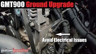
Typical fix: Clean the ground connection point and the terminal with a wire brush, then secure it tightly. Apply dielectric grease to prevent future corrosion. 🎬 Watch: How to properly clean and upgrade GM grounds
Est. part cost: $1-$5
Rare But Worth Checking
- Faulty Diagnostic Link Connector (DLC): The TSB PIT5076E mentions that a faulty MDI (Multiple Diagnostic Interface) cable or a problem with the DLC port itself can sometimes prevent codes from clearing and mimic a bus fault. While this is more of a diagnostic challenge, a damaged DLC port could have internal wiring issues.
- Aftermarket Devices: A user on CorvetteForum with a similar GM system noted that aftermarket modifications, like a subwoofer system, can sometimes interfere with module communication if not installed correctly, potentially causing bus errors.
Diagnosis Steps
- Connect a professional scan tool to read all codes from all modules. Note which modules are not communicating.
- Check battery voltage to ensure it's stable (12.6V off, 13.7-14.7V running), as low voltage can cause communication errors.
- Turn the ignition off and wait at least 2 minutes for the network to go to sleep. At the DLC, measure the resistance between Pin 6 (CAN High) and Pin 14 (CAN Low). A healthy high-speed CAN network should read approximately 60 ohms.
- If the resistance is 120 ohms, it indicates an open circuit or a missing terminating resistor (one of the main modules like the EBCM or BCM may be disconnected or faulty). If it's near 0 ohms, it suggests a short between the CAN high and low wires.
- Crucial Step for this Platform: Following TSB PIT5457B, inspect the wiring harness under the driver's and passenger's front door sill plates. Look for opens or high resistance in the Communication Enable circuit (Circuit 5986). Test for ~12V on this circuit at the EBCM or PSCM connector with the key on.
- If wiring appears intact, use a wiring diagram to locate the modules on the chassis bus. Disconnect them one at a time, re-measuring the bus resistance each time to see if the reading returns to normal. This can help isolate a faulty module that is pulling the network down.
- For advanced diagnosis, use an oscilloscope to view the CAN High and CAN Low signals at the DLC. This can reveal signal integrity problems like shorts to power/ground or interference that a multimeter would miss.
Parts You'll Likely Need
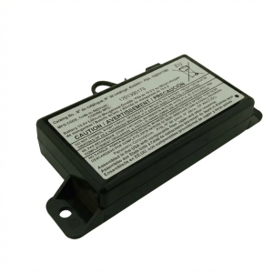
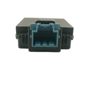
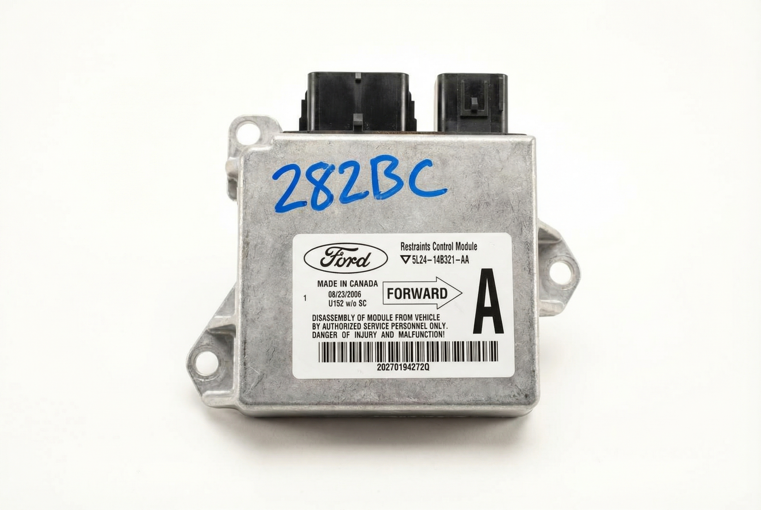
- Electronic Brake Control Module (EBCM)
(OEM #84065240 (supercedes older numbers for 2012 model year, verify with VIN))— If the module itself has failed internally, it can bring down the entire chassis bus. This is a common point of failure after wiring issues have been ruled out. Requires programming after installation.
Trusted brands: ACDelco
OEM price range: $500-$950
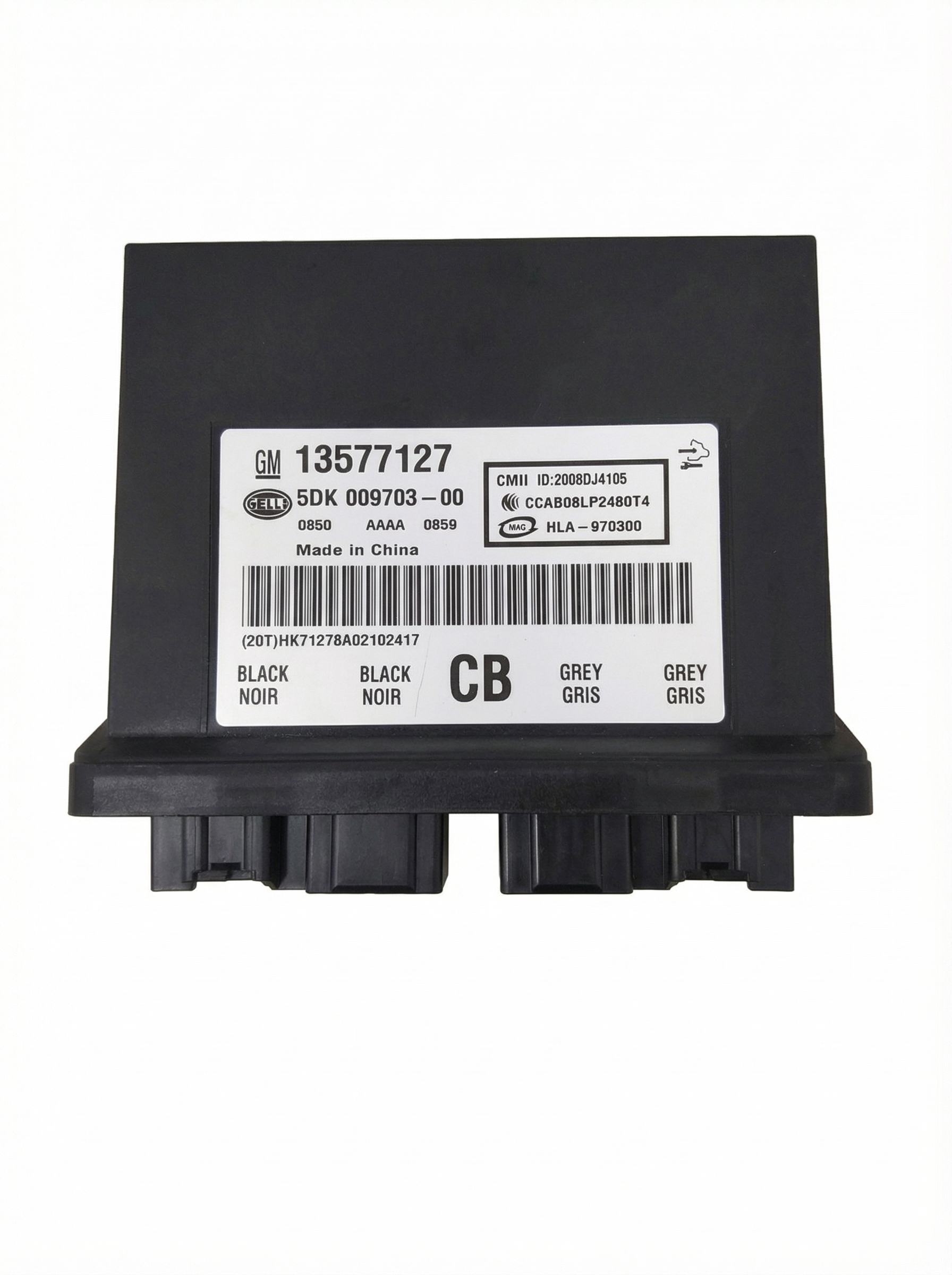
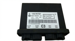
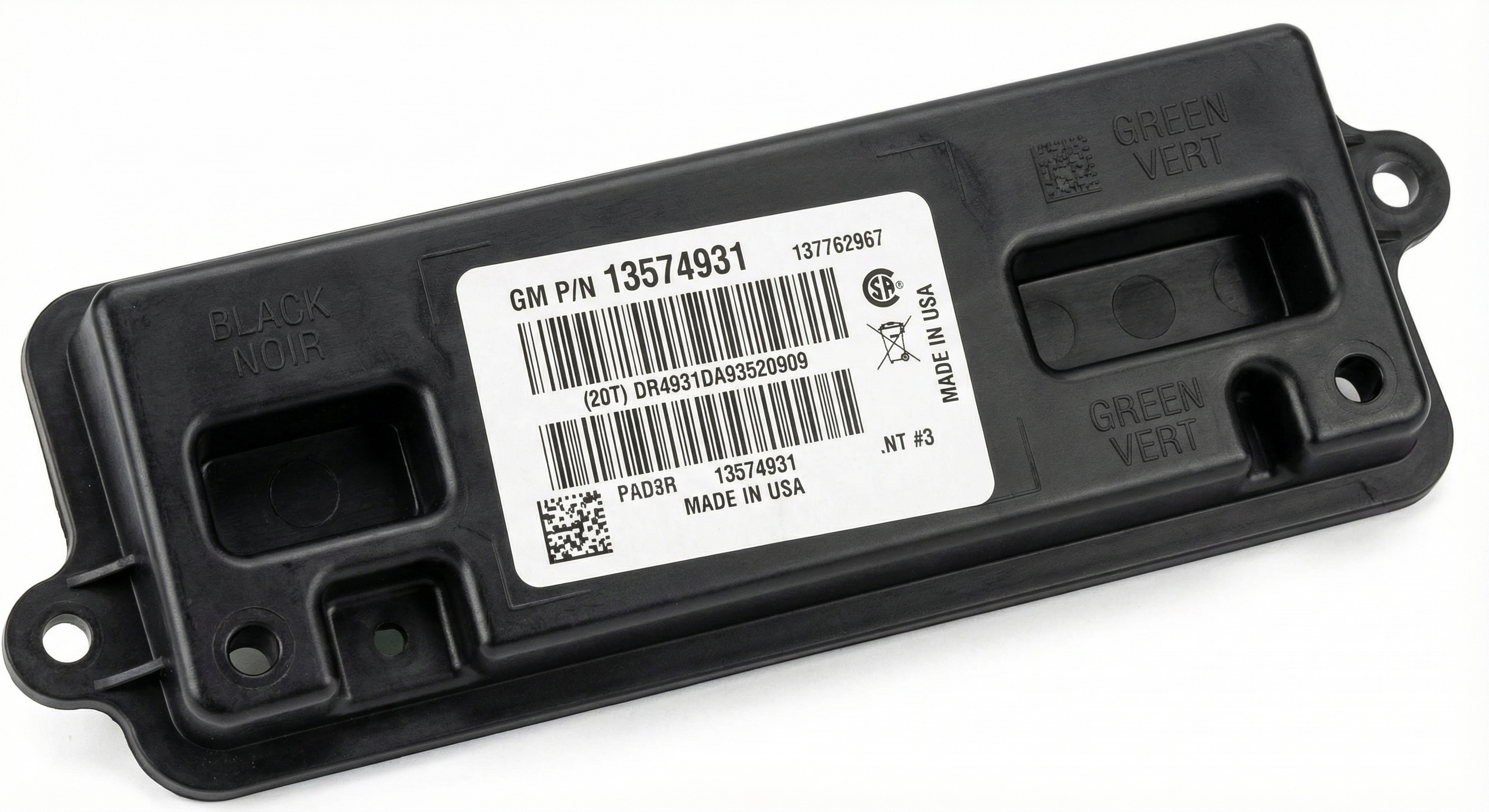
Aftermarket price range: $400-$800 - Power Steering Control Module (PSCM)
(OEM #84024543 (supercedes 20756000, 22804071, 22928962 for 2012-2016 models, verify with VIN))— Similar to the EBCM, an internal fault in the PSCM can disrupt network communication, triggering a U0077 code. This module also requires programming.
Trusted brands: ACDelco
OEM price range: $120-$200
Aftermarket price range: $100-$180 - Wiring Harness Repair Supplies — If the cause is a broken wire or corroded connector under the sill plates, only basic supplies like wire, terminals, and heat shrink tubing are needed. This is the most likely required 'part'.
OEM price range: $10-$50
Aftermarket price range: $10-$50
Related Codes That Often Appear With This One
- C0710 — Often seen with a 'Service Steering' message, indicating a fault related to the steering angle sensor, which communicates on the chassis bus.
- U0121 — Indicates lost communication with the Electronic Brake Control Module (EBCM). This is frequently seen with U0077 as the EBCM is a key module on the chassis bus.
- U0131 — Indicates lost communication with the Power Steering Control Module (PSCM). This is also commonly paired with U0077.
- U0074, U0125, U0126 — These are other general CAN bus communication codes that can appear alongside U0077, as noted in TSB PIT5076E and PIT5457, indicating a widespread network problem.
Technical Service Bulletins (TSBs) & Recalls
- PIT5076E: Addresses multiple communication DTCs, including U0077, that may set and not clear. It advises diagnosing the Chassis bus and checking the diagnostic tool's cable connection.
- PIT5457B: (Supersedes PIT5457 and PIT5457A) Points to high resistance or an open in the Communication Enable circuit (5986) under the driver's or passenger's sill plate as a cause for U0077 and loss of communication with chassis modules.
Platform-Specific Known Issues
- TSB PIT5076E specifically notes that U0077 can appear with other codes after attempting to learn the steering angle sensor, and directs technicians to diagnose the Chassis bus before replacing parts.
- TSB PIT5457B is highly relevant, pointing to a specific wiring failure in the Communication Enable circuit (5986) under the driver's and passenger's sill plates as a direct cause for U0077 and loss of communication with the EBCM and
Mechanic-Grade Diagnostic Values
- CAN Bus Resistance at DLC — expected: ~60 Ω. Failure: 120 Ω indicates an open in the bus or a missing termination resistor. ~0 Ω indicates a short between CAN High and CAN Low wires.
- Communication Enable Circuit (Circuit 5986) Voltage — expected: Approximately 12V with key in ACC, ON, or START.. Failure: Low or no voltage indicates an open or high resistance in the circuit, likely under the sill plates.
- Communication Enable Circuit (Circuit 5986) Load Test — expected: The circuit should light a 194 bulb and maintain at least 11V across the bulb.. Failure: If the bulb does not light or voltage drops below 11V, the circuit has high resistance and cannot support the module's communication needs.
- CAN High (Pin 6 at DLC) to Ground Voltage — expected: ~2.5V (recessive state, no data), fluctuates to 3.5V (dominant state).. Failure: Stuck high, stuck low, or no voltage. Requires an oscilloscope for accurate measurement.
- CAN Low (Pin 14 at DLC) to Ground Voltage — expected: ~2.5V (recessive state, no data), fluctuates to 1.5V (dominant state).. Failure: Stuck high, stuck low, or no voltage. Requires an oscilloscope for accurate measurement.
Scan Tool Commands That Help
- GDS2 (GM Global Diagnostic System 2): Hybrid Battery Pack Cooling Fan active test — On hybrid models, this allows a technician to command the battery cooling fan on to verify its operation, which is controlled over the CAN bus. While not directly for U0077, it demonstrates the bidirectional control capability for modules on the network.
- GDS2 (GM Global Diagnostic System 2): Module Status — To see a list of all expected control modules on the network and query their communication status (Present, Not Present). This is the first step in identifying which module has dropped off the bus.
Wiring & Ground Locations
- Splice J365 — Under the passenger front sill plate.. This is a known high-resistance point for the Communication Enable circuit (5986), which can cause modules on the chassis bus to lose power and stop communicating, setting a U0077.
- Wiring Harness under Driver's Sill Plate — In the channel under the driver's side front door sill plate.. This is the other primary location identified in TSB PIT5457C where the Communication Enable circuit (5986) is known to corrode or break, causing this code.
- G103 — At the left rear of the engine compartment on the cowl, above the brake booster.. This is a major ground point for the Body Control Module (BCM) and the Data Link Connector (DLC). A poor connection here can cause widespread communication issues.
- EBCM Ground — Often located on the frame rail near the EBCM itself, typically under the front of the vehicle. Specific location may require a service manual lookup, but a common GM location is on the passenger side under the bumper skin, designated G107 on similar platforms.. The Electronic Brake Control Module (EBCM) is a terminating resistor on the bus. A bad ground can cause it to malfunction and disrupt the entire network.
OEM Part Supersession History
20756000, 22804071, 22928962→84024543— Standard part evolution, design improvements.
Heads up: This part is for the Power Steering Control Module (PSCM). It requires programming and/or special setup procedures after installation using GM Service Information.
Model Year Variations Within This Range
- 2012: NHTSA Recall 11V404000 was issued for some 2012 LaCrosse models due to an incorrect software calibration in the EBCM that could cause StabiliTrak to activate unexpectedly. The fix was reprogramming the EBCM. An unresolved software issue could potentially cause communication faults.
- 2014: A recall (NHTSA 14V252) was issued for some 2014 models for an unsealed wiring splice in the driver's door harness that could corrode and break, affecting circuits for the door chime and Retained Accessory Power (RAP). This indicates a potential wiring vulnerability in that model year.
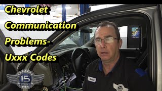
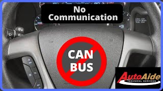
Helpful Videos
We Have This Part in Stock

The information in this article is provided for general reference and educational purposes only. Vehicle specifications, procedures, and part compatibility can vary by production date, trim level, and region. Always consult your vehicle's factory service manual and verify part numbers before purchasing or performing repairs. Safety-critical components such as airbags, seat belts, and braking systems should be installed by a qualified professional.
- Buick LACROSSE:
- 🧭 Diagnostic Flowchart
- 🎬 Helpful Videos
- 🛍️ Shop This Part
- What's Unique About the 2010-2015 Buick LACROSSE
- Symptoms You May Notice
- Most Likely Causes
- Rare But Worth Checking
- Diagnosis Steps
- Parts You'll Likely Need
- Related Codes That Often Appear With This One
- Technical Service Bulletins (TSBs) & Recalls
- Platform-Specific Known Issues
- Mechanic-Grade Diagnostic Values
- Scan Tool Commands That Help
- Wiring & Ground Locations
- OEM Part Supersession History
- Model Year Variations Within This Range
- 🎟️ Get 5% Off