
U0077 on 2011-2015 Buick Regal: Chassis Communication Bus Failure Causes and Fixes
U0077 on a Buick Regal indicates a total communication failure on the chassis network, which controls ABS and power steering. This is a serious code that makes the vehicle unsafe to drive. The cause is almost always a wiring issue, such as a broken, corroded, or chafed wire, not a failed module. Specifically, a wire known as the 'Communication Enable' circuit is often the culprit.
- U0077 is a critical safety code indicating a failure of the network for your ABS and power steering. Do not drive the vehicle.
- The problem is most likely a wiring issue (chafed, broken, or corroded wire), not a failed computer module.
- A thorough inspection of the wiring harness behind the dashboard and under the door sill plates is the most important diagnostic step.
- Do not replace any expensive modules until a full electrical diagnosis has confirmed the wiring is 100% intact.
- Due to the complexity of network diagnostics, professional service from a technician experienced with GM electrical systems is highly recommended.
What's Unique About the 2011-2015 Buick REGAL
On this generation of Buick Regal and its Epsilon II platform mates, the U0077 code is rarely caused by an expensive control module failure. Instead, it's most often traced back to a specific wiring problem. Technical Service Bulletin PIT5457B details how the 'Communication Enable' circuit (Circuit 5986) is prone to developing high resistance or an open circuit. This wire is frequently damaged by corrosion under the driver or passenger door sill plates, making a thorough inspection of this specific circuit the most critical diagnostic step.
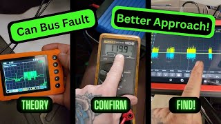
🎬 See how to troubleshoot Chevrolet communication problems and U-codes.Diagnostic Flowchart
Tap your situation to follow the diagnostic path that matches what you're seeing on this vehicle.
Symptoms You May Notice
- ABS warning light is on
- StabiliTrak / Traction Control warning light is on
- Service Power Steering message or warning light
- Loss of power steering assist, making steering very heavy
- Multiple warning lights appearing on the instrument cluster simultaneously
- Backup camera may become inoperative
- Replacing the EBCM or PSCM before performing a thorough wiring inspection. The root cause is far more likely to be a simple wiring fault in Circuit 5986 that is much cheaper to fix.
Most Likely Causes
- Damaged or Corroded 'Communication Enable' Wire (Circuit 5986) 🔴 High Probability GM TSB PIT5457B specifically identifies this circuit as a common failure point. It runs in vulnerable channels under the front door sill plates where water can intrude, leading to corrosion and an open circuit. Splice J365, under the passenger front sill plate, is a known point of corrosion.
How to confirm: Visually inspect the wiring harness under the driver and passenger door sill plates for a purple wire (may vary, check diagram) showing signs of damage or green/white corrosion. With the key on, use a multimeter to check for ~12 volts on Circuit 5986 at the EBCM or PSCM connector. No voltage or low voltage points to a break in this wire. Also, measure resistance between Pin 6 and Pin 14 at the DLC; it should be 60 ohms. TSB PIT5457D suggests load testing Circuit 5986 with a small bulb (e.g., a 194 bulb); if the bulb fails to light despite a 12V reading, it confirms high resistance in the circuit.
Typical fix: Repair the broken, shorted, or corroded section of Circuit 5986. This involves cutting out the damaged section, splicing in a new piece of wire using weatherproof butt connectors or solder and heat shrink, and securing the harness. Cleaning or replacing corroded splice points like J365 may be necessary.
Est. part cost: $10-$50 - Faulty Electronic Brake Control Module (EBCM) ⚪ Low Probability → Shop ABS Control Module
How to confirm: After confirming the wiring is intact (including Circuit 5986) and has proper resistance (60 ohms), disconnect the EBCM. If communication with other modules on the bus is restored (which can be checked with a capable scan tool), the EBCM is likely faulty and shorting the network internally. This is an advanced diagnostic step.
Typical fix: Replace the Electronic Brake Control Module. The new module will require programming to the vehicle's VIN.
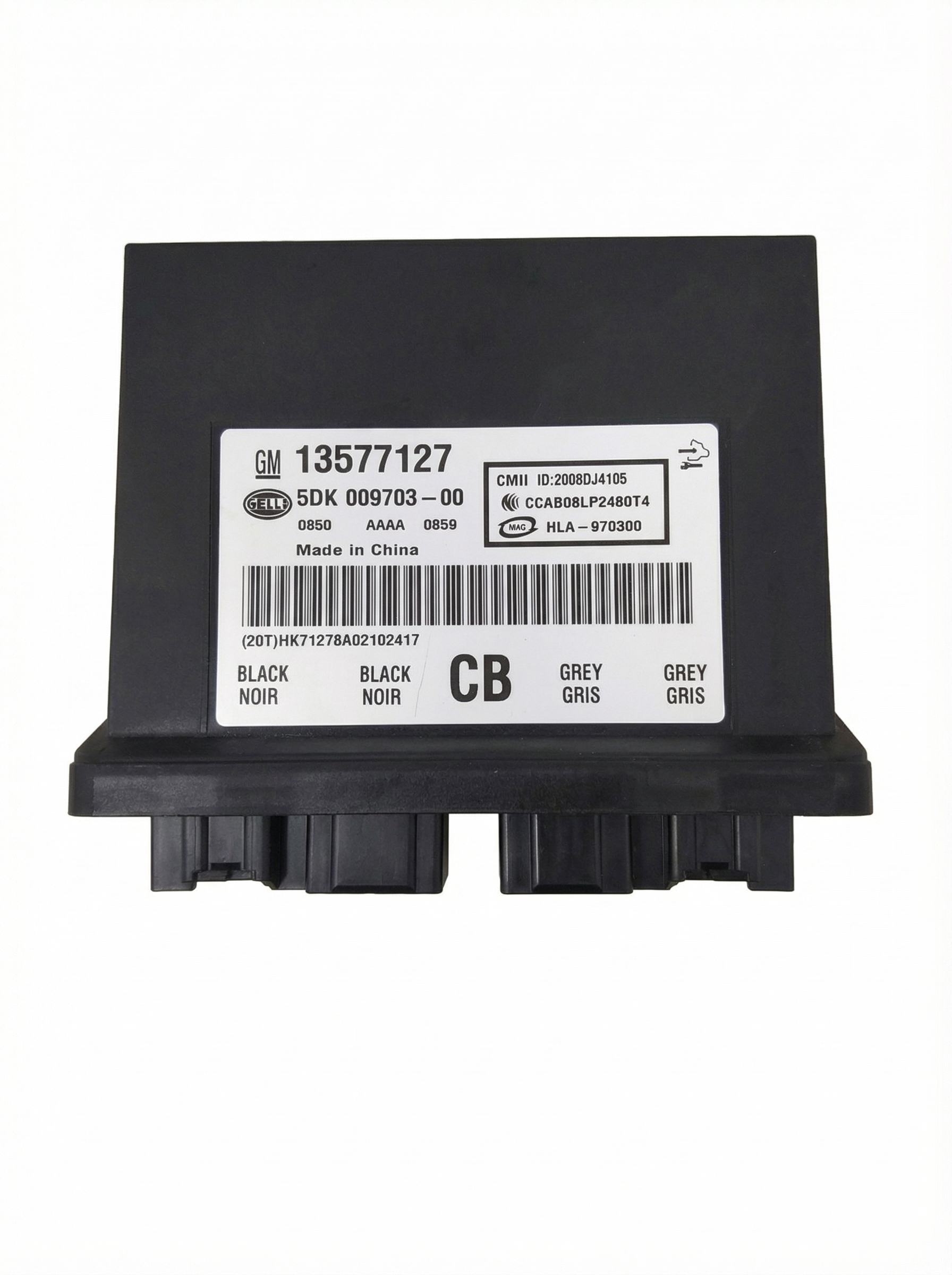
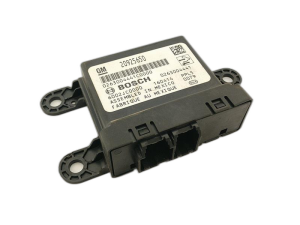
Est. part cost: $300-$700 - Faulty Power Steering Control Module (PSCM) ⚪ Low Probability → Shop Power Steering Control Module
How to confirm: Similar to the EBCM, disconnect the PSCM after verifying the wiring is good. If communication on the bus returns, the PSCM is the likely cause of the network failure. This is typically located on the steering rack or column and may be difficult to access.
Typical fix: Replace the Power Steering Control Module. This part often requires programming to function correctly.
Est. part cost: $250-$600
Rare But Worth Checking
- Poor ground connection for the BCM or other related modules
- Bent or spread terminal pin at a module electrical connector, such as the EBCM or PSCM.
- Faulty diagnostic MDI cable giving a false 'no communication' reading.
Diagnosis Steps
- Scan for all DTCs in all modules. Note all 'U' (network) codes and any codes stored in the EBCM and PSCM.
- Check battery voltage and ground connections. Ensure voltage is stable (12.4V+ off, 13.7-14.7V running). A weak battery or poor ground can cause various electrical issues.
- Gain access to a wiring diagram for the chassis CAN bus and the Communication Enable circuit (5986).
- Locate the diagnostic link connector (DLC) and use a multimeter to measure the resistance between Pin 6 (CAN High) and Pin 14 (CAN Low). A healthy network should read approximately 60 ohms.
- If resistance is 120 ohms, it indicates a break in the circuit or a missing terminating resistor. If resistance is near 0 ohms, it indicates a short between the two CAN lines.
- Crucially, inspect the Communication Enable circuit (Circuit 5986). Following TSB PIT5457B, remove the driver and passenger front door sill plates and inspect the wiring harnesses for a broken or corroded wire. Pay special attention to splice J365 under the passenger sill plate.
- Test for voltage on Circuit 5986 at the EBCM or PSCM connector. With the key on, you should see battery voltage (~12V). If voltage is present, load test the circuit with a small 194 bulb to check for high resistance; if the bulb doesn't light, the wire is faulty.
- If a damaged section of wire is found, perform a proper repair using solder and heat shrink or a high-quality weatherproof butt connector.
- If no wiring damage is found, inspect connector terminals at the EBCM and PSCM for spread or corroded pins that could cause an intermittent connection.
- If wiring and connectors are good, the next step is to isolate modules. Disconnect one module at a time (e.g., the EBCM) and re-check the bus resistance to see if it returns to a normal value. This can identify a module that is internally shorting the network.
- After repairs, clear all DTCs and perform a test drive, including a Steering Angle Sensor learn procedure if required, to ensure the fault does not return.
Parts You'll Likely Need
- Wiring Repair Supplies — The most common cause is a break or corrosion in the chassis CAN bus wiring, specifically Circuit 5986, requiring a splice repair.
Trusted brands: 3M
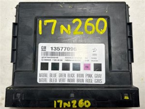
Aftermarket price range: $10-$50 - Electronic Brake Control Module (EBCM)
(OEM #84107111 (supercedes 23227008, 23210878, among others for 2012 model year))— In the rare case that the module itself has failed and is shorting the communication network, it will need to be replaced. This should only be done after confirming the wiring is good.
Trusted brands: ACDelco
OEM price range: $450-$700
Aftermarket price range: $300-$500 - Power Steering Control Module (PSCM)
(OEM #84024543 (supercedes 22928962, 20756000 for 2012 model year))— A rare cause of failure. If the module shorts the bus internally, it must be replaced after wiring is confirmed to be intact.
Trusted brands: ACDelco
OEM price range: $120-$200
Aftermarket price range: $80-$150
Related Codes That Often Appear With This One
- U0121 — Lost Communication With Electronic Brake Control Module. This is expected when the chassis bus (U0077) goes down.
- U0131 — Lost Communication With Power Steering Control Module. This is also expected when the chassis bus (U0077) fails.
- U0125 — Lost Communication With Yaw Rate Sensor Module. This module is on the chassis bus, so a bus failure (U0077) will cause this code.
- U0126 — Lost Communication With Steering Angle Sensor Module. This sensor is critical for stability control and is on the chassis bus.
- C0186 — Lateral Accelerometer Circuit. This code can be set in the EBCM when communication is lost.
- C0196 — Yaw Rate Circuit. This code can be set in the EBCM when communication is lost.
- C0710 SYM71 — A symptom code found in the EBCM or PSCM that indicates a fault related to the chassis bus, often seen with U0077.
Technical Service Bulletins (TSBs) & Recalls
- PIT5076E: Mentions U0077 in the context of diagnosing Chassis bus faults when other brake or steering codes are present.
- PIT5457B: Details the common failure of the Communication Enable circuit (5986) under the sill plates as a primary cause for U0077 and related communication codes on this and similar GM platforms.
Platform-Specific Known Issues
- TSB #PIT5076E specifically lists U0077 as a code that points to a fault on the 'Chassis bus' when diagnosing issues with the electronic brake or power steering control modules.
- TSB #PIT5457B provides critical diagnostic direction for U0077, pointing to an open/high resistance on the 'Communication Enable' circuit (5986). It identifies common failure points under the driver's and passenger's front sill plates, including splice J365.
Mechanic-Grade Diagnostic Values
- GMLAN Bus Voltage (High/Low wires) — expected: Approx. 2.5V on each wire at rest (recessive state). During communication (dominant state), CAN High goes to ~3.5V and CAN Low goes to ~1.5V.. Failure: Voltages stuck high, low, or at zero indicate a short or open on the bus.
- Communication Enable Circuit (5986) Load Test — expected: The circuit should illuminate a small test bulb (like a 194 bulb) when connected between the circuit at a module and a good ground with the key on.. Failure: If a voltmeter reads ~12V but the bulb does not light, it confirms high resistance in the circuit, which is a common cause of U0077.
Hidden / Shadow Codes Worth Checking
- C0710 SYM71: A manufacturer-specific symptom code that can be set in the Electronic Brake Control Module (EBCM) or Power Steering Control Module (PSCM). It is often found alongside U0077 and directs technicians to diagnose the chassis bus. (see via Requires a dealer-level scan tool like the GM GDS2/Tech2 to view module-specific symptom codes.)
Scan Tool Commands That Help
- GM GDS2 / Tech2: Module Communication Status / Data Display — To view the status of all modules on the network in real-time. This helps identify which specific modules are not communicating, narrowing down the diagnostic path.
- GM GDS2 / Tech2: Steering Angle Sensor (SAS) Learn — After repairs are completed, especially if the EBCM or PSCM were disconnected or replaced. A loss of communication can cause the SAS to lose its calibration, and this procedure is required to restore StabiliTrak functionality.
Wiring & Ground Locations
- Splice J365 — Under the passenger front door sill plate, within the main wiring harness channel.. This is a known point of failure where the Communication Enable circuit (5986) can corrode and develop high resistance, causing all modules on the chassis bus to stop communicating.
- PSCM Connector X1, Pin 2 — At the Power Steering Control Module (K43), which is typically on the steering rack or column.. This is the specific pin for the 'Serial Data Communication Enable' circuit (5986). It is a perfect, accessible point to test for the required ~12V signal when diagnosing a bus failure.
- Ground G218 (Potential Issue) — Under the driver's side dashboard, often behind the A-pillar trim panel.. On similar GM platforms, this ground is a known trouble spot where sound-deadening material was sometimes installed under the ground lug at the factory, leading to high resistance and intermittent communication faults across multiple modules.
Real Owner Repair Stories
- YouTube channel 'Advanced Level Diagnostics' / CorvetteForum user (2019 Chevrolet Tahoe / 2017 Chevrolet Corvette (similar GM CAN architecture)) — Multiple 'U' codes including U0077, no communication with EBCM and other chassis modules, bus resistance showing 120 ohms (open circuit).
❌ Tried (didn't work) Initial scan pointed to a module failure or a complete break in the wiring harness.
✅ What actually fixed it The fault was intermittent and could be triggered by wiggling a harness connector. The root cause was a single spread (loose) female terminal pin inside the EBCM connector. Tightening the pin to ensure a solid connection with the male pin restored the bus resistance to 60 ohms and resolved all codes.
"I Checked Everything" — The Actual Cause
- Cases exist where all wiring tests for continuity (ohms) pass, but the code persists. The actual cause was found to be a physically loose or 'spread' female pin inside a module connector (like the EBCM), which would lose contact intermittently with vehicle vibration. A visual inspection and 'wiggle test' of connectors is crucial.
- Technicians have reported chasing U0077 and other communication codes that refuse to clear, only to find the issue was a faulty MDI cable (the diagnostic interface itself), not a problem with the vehicle's wiring or modules. Trying a different, known-good MDI cable resolved the issue.
Helpful Videos
We Have This Part in Stock

The information in this article is provided for general reference and educational purposes only. Vehicle specifications, procedures, and part compatibility can vary by production date, trim level, and region. Always consult your vehicle's factory service manual and verify part numbers before purchasing or performing repairs. Safety-critical components such as airbags, seat belts, and braking systems should be installed by a qualified professional.
- Buick REGAL:
- 🧭 Diagnostic Flowchart
- 🎬 Helpful Videos
- 🛍️ Shop This Part
- What's Unique About the 2011-2015 Buick REGAL
- Symptoms You May Notice
- Most Likely Causes
- Rare But Worth Checking
- Diagnosis Steps
- Parts You'll Likely Need
- Related Codes That Often Appear With This One
- Technical Service Bulletins (TSBs) & Recalls
- Platform-Specific Known Issues
- Mechanic-Grade Diagnostic Values
- Hidden / Shadow Codes Worth Checking
- Scan Tool Commands That Help
- Wiring & Ground Locations
- Real Owner Repair Stories
- "I Checked Everything" — The Actual Cause
- 🎟️ Get 5% Off