
U0077 on 2010-2015 Cadillac SRX: Chassis Bus Communication Failure Causes and Fixes
This code indicates a total communication failure on the chassis network, affecting safety systems like ABS and power steering. The most likely cause is a wiring problem (corrosion, short, or break), often located under the driver or passenger side sill plates in a specific wire (Circuit 5986). Diagnosis is critical before replacing any expensive modules.
- U0077 is a critical network failure code for safety systems; do not drive the vehicle.
- The problem is very often a broken or corroded wire, not an expensive module failure.
- A thorough inspection of the wiring under the driver and passenger sill plates is the number one diagnostic step.
- Do not replace any modules until a complete network diagnosis has been performed to isolate the exact point of failure.
- This is not a DIY-friendly repair for beginners due to the complex electrical diagnosis required.
What's Unique About the 2010-2015 Cadillac SRX
The 2010-2016 Cadillac SRX and its direct platform mate, the 2011 Saab 9-4X, are built on the GM Theta Premium platform, which blends elements of the standard Theta and Epsilon II architectures. On these vehicles, the U0077 code is very often not caused by a failed module, but by a specific wiring failure. Multiple Technical Service Bulletins (TSBs) for related GM platforms point to an open or high-resistance fault in the 'Communication Enable' circuit (Circuit 5986), a purple wire that 'wakes up' the modules on the chassis bus. This wire is notoriously prone to corrosion and breakage where it runs in the channel under the driver and passenger front door sill plates.
Diagnostic Flowchart
Tap your situation to follow the diagnostic path that matches what you're seeing on this vehicle.
Symptoms You May Notice
- "Service StabiliTrak" message on the driver information center
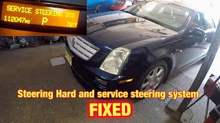
- "Service Power Steering" message
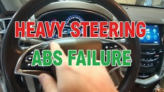
- ABS and Traction Control warning lights are illuminated
- Loss of power steering assist, making the wheel very hard to turn 🎬 Watch: How to fix heavy steering and the service message.
- Backup camera may be inoperative or lose guidance lines
- Vehicle Settings icon in the infotainment system may be grayed out
- Replacing the Electronic Brake Control Module (EBCM) or Power Steering Control Module (PSCM) without first performing a full network diagnosis. The code often points to a wiring issue, not a module failure, and replacing a module will not fix a broken wire. This is a costly and common mistake.
Most Likely Causes
- Open, Short, or High Resistance in Chassis CAN Bus Wiring 🔴 High Probability GM TSBs for similar platforms identify common failure points for wiring harnesses, particularly the 'Communication Enable' circuit (5986, typically a purple wire) which can corrode or break under the sill plates or get pinched elsewhere in the chassis harness. Water and salt can get trapped in the wiring channel under the door sills, causing the wire to degrade.
How to confirm: Visually inspect the wiring harness under the driver and passenger front sill plates for signs of corrosion (green crust) or damage. A multimeter can be used to check for approximately 12 volts on the communication enable circuit (purple wire) at a module connector (like the EBCM) with the key on. One can also check for proper resistance (approx. 60 ohms) across the CAN bus pins (6 and 14) at the DLC.
Typical fix: Repairing the damaged section of the wiring harness and protecting it from future moisture intrusion. This is often a low-cost parts fix but can be labor-intensive to locate.
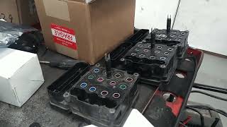
Est. part cost: $5-$50 - Faulty Control Module 🟡 Medium Probability Any module on the chassis bus (EBCM, PSCM, etc.) can fail internally, causing it to short out the communication network and prevent other modules from talking. The EBCM is a common point of failure, sometimes due to internal cracks or water intrusion.
How to confirm: If the CAN bus wiring and the Communication Enable circuit test good, a technician will disconnect modules from the chassis bus one by one. When the faulty module is disconnected, the rest of the network will resume communication. This is the definitive test before replacing a module.
Typical fix: Replacement of the failed module (e.g., EBCM or PSCM). The new module will require programming to the vehicle. 🎬 Watch: How to program a replacement ABS module. Some companies offer a rebuild service for the original module.
Est. part cost: $300-$900 - Poor Ground Connection or Low Battery Voltage ⚪ Low Probability → Shop Vehicle Battery
How to confirm: Test the vehicle's battery to ensure it has at least 12.4 volts with the engine off and maintains stable voltage. Inspect and clean major chassis and module ground points, especially those in the engine bay and near the affected modules.
Typical fix: Clean and tighten ground connections or replace a weak battery.
Est. part cost: $0-$250
Rare But Worth Checking
- Faulty Body Control Module (BCM): → Shop Body Control Module
Diagnosis Steps
- Connect a professional scan tool capable of reading all vehicle modules. Record all present DTCs, especially the 'U' codes.
- Check battery voltage and inspect main power and ground connections for tightness and corrosion.
- Following guidance from GM TSBs like PIT5457, carefully remove the driver and passenger front sill plates and peel back the carpet. Inspect the wiring harnesses in the channel for signs of water intrusion, corrosion (green powder/crust), or physical damage. Pay extremely close attention to the purple wire (Circuit 5986).
- If a fault is found, repair the affected wires. If no visible fault is found, proceed with electrical testing.
- With the key on, use a multimeter to check for ~12V on the purple wire (Circuit 5986) at an easily accessible module, like the EBCM connector. If voltage is low or absent, the break is between the BCM and that point.
- With the battery disconnected, measure the resistance between Pins 6 and 14 (High Speed CAN High and CAN Low) at the OBD-II port. A healthy network should read approximately 60 ohms. A reading of 120 ohms indicates a break in the circuit or a missing terminating resistor. A reading near 0 ohms indicates a short circuit.
- If the resistance is incorrect, begin disconnecting modules on the Chassis Expansion Bus (EBCM, PSCM, etc.) one at a time while monitoring the resistance. If the resistance returns to a normal value after disconnecting a module, that module is likely the source of the fault.
- If all wiring and resistance checks pass, the issue may be an intermittent connection that only appears under certain conditions (vibration, temperature). Wiggle testing the harness while monitoring network status may be necessary.
Parts You'll Likely Need
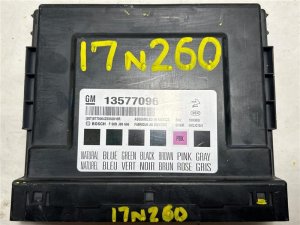
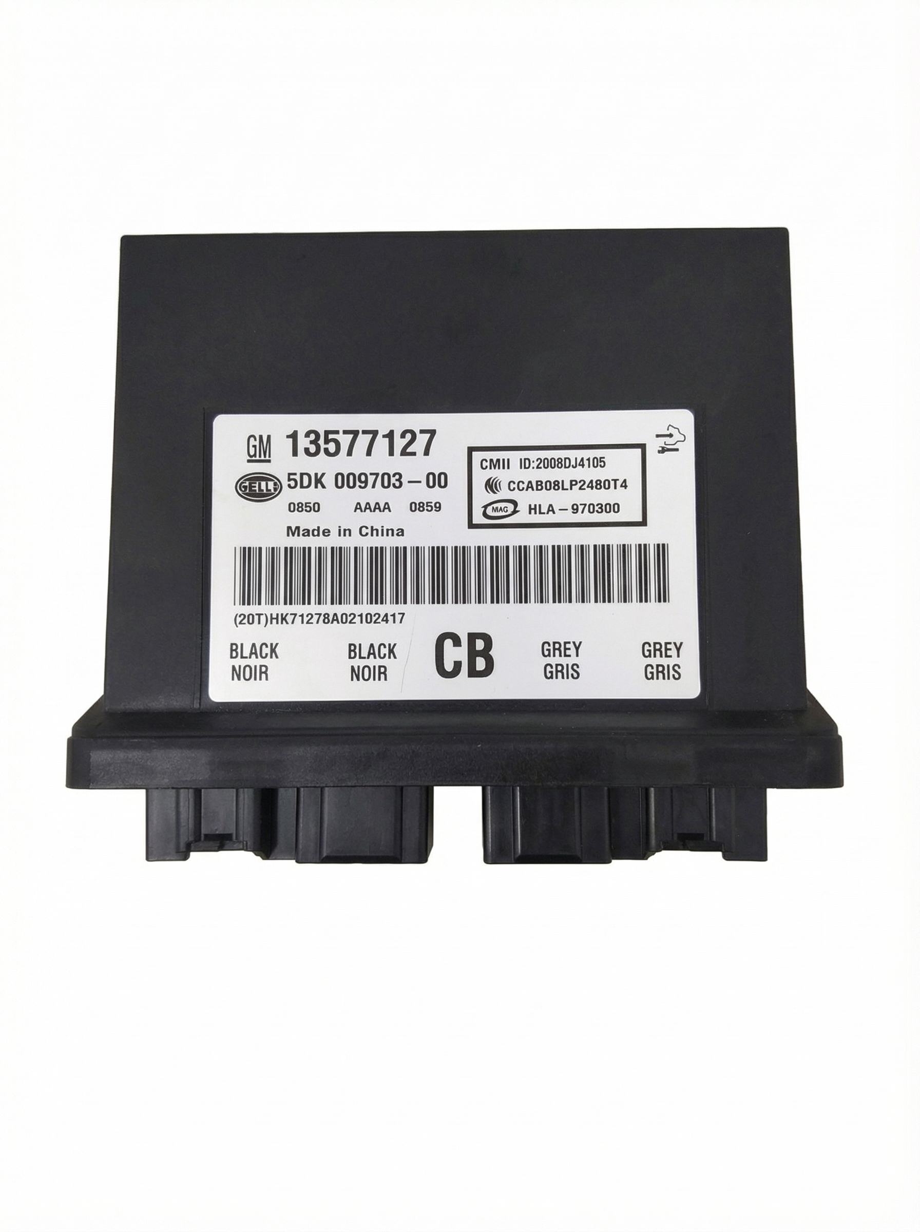
- Electronic Brake Control Module (EBCM)
(OEM #20842710, 23137198, 22752525 (Verify by VIN))— This is one of the primary modules on the chassis bus. It can fail internally and short the network, but should only be replaced after confirming it is the cause of the failure via diagnostic isolation. Part is often discontinued or remanufactured.
Trusted brands: ACDelco (Genuine GM)
OEM price range: $500-$900
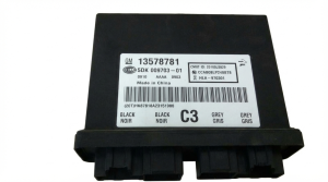
Aftermarket price range: $300-$600 - Power Steering Control Module (PSCM) — Another critical module on the chassis bus that can cause a network-down situation if it fails. It must be diagnosed as the specific point of failure before replacement.
Trusted brands: ACDelco
OEM price range: $350-$700
Aftermarket price range: $250-$500 - Wiring Repair Supplies — If the cause is the common wiring failure, you will need wire, butt connectors, heat shrink tubing, and electrical tape to perform a durable repair.
Trusted brands: 3M
OEM price range: $10-$30
Aftermarket price range: $5-$20
Related Codes That Often Appear With This One
- U0121 — Lost Communication With Electronic Brake Control Module (EBCM)
- U0131 — Lost Communication With Power Steering Control Module (PSCM)
- U0125 — Lost Communication With Yaw Rate Sensor Module
- U0126 — Lost Communication With Steering Angle Sensor Module
- C0186 — Lateral Accelerometer Circuit Malfunction
- C0196 — Yaw Rate Circuit Malfunction
Technical Service Bulletins (TSBs) & Recalls
- PIT5076E: Mentions that if U0077 is set and will not clear, the Chassis bus must be diagnosed. This is the most direct TSB for this vehicle and code.
- PIT5457C: While for other GM models, it provides critical diagnostic insight into a common cause for U0077: an open/short in the Communication Enable circuit (5986), often found under the sill plates. It details checking for voltage and known chafe/corrosion points.
- 10-00-89-005: A general GM bulletin referenced by other TSBs that provides standard procedures and warranty information for wire and connector repairs.
Platform-Specific Known Issues
- A known issue on the 2010-2015 Cadillac SRX, documented in TSB #PIT5076E, involves code U0077 setting along with other chassis codes, prompting a diagnosis of the Chassis bus.
- While not for the SRX specifically, related GM TSBs (like PIT5457) for other vehicles of the same era detail frequent failures of the 'Communication Enable' circuit (5986) due to corrosion under the sill plates, which is a highly probable cause for this issue on the SRX as well.
Mechanic-Grade Diagnostic Values
- Chassis Expansion CAN Bus Resistance — expected: ~60 Ohms. Failure: 120 Ohms indicates an open circuit or a module/terminating resistor is offline. Near 0 Ohms indicates a short between the two CAN lines.
- High Speed GMLAN Resistance — expected: ~60 Ohms. Failure: 120 Ohms indicates an open circuit. Near 0 Ohms indicates a short between CAN High and CAN Low.
- Communication Enable Circuit (5986) Voltage — expected: Approx. 12 Volts. Failure: Low or no voltage indicates an open/short in the circuit or a faulty BCM driver.
- Communication Enable Circuit (5986) Current Draw — expected: Less than 0.88 amps. Failure: A draw exceeding 0.88 amps will cause the BCM to shut down the circuit driver, leading to a U0077 code.
- Module Ground Resistance — expected: Less than 1.0 Ohm. Failure: Resistance higher than 1.0 Ohm indicates a poor ground connection, which can cause communication faults.
Hidden / Shadow Codes Worth Checking
- Symptom Code 71: A manufacturer-specific code that can be set in the Electronic Brake Control Module (EBCM) or Power Steering Control Module (PSCM) alongside U0077. (see via This code is visible using a dealer-level scan tool like the GM GDS2/Tech2 when interrogating the specific modules on the chassis bus. It is mentioned in TSB #PIT5076E.)
Scan Tool Commands That Help
- GM GDS2 / Tech2: Module Communication Status / Data Display — To see a list of all modules on the Chassis Expansion Bus and which ones are actively communicating. If a module is not reporting, it helps isolate the point of failure. This is a primary step before performing physical wiring checks.
- GM GDS2 / Tech2: Module 'Talk-Back' or Ping Test — Some scan tools allow you to send a direct command (ping) to a specific module to see if it responds. If a module on the chassis bus fails to respond to a direct command while others do, it points towards an issue with that specific module or its direct wiring.
Wiring & Ground Locations
- Circuit 5986 — A purple wire that runs from the BCM to all modules on the Chassis Expansion Bus. It is commonly found to be corroded or broken in the wiring channel under the driver and/or passenger front door sill plates.. This is the 'Communication Enable' circuit. It provides a 12V wake-up signal to the modules. An open or short on this wire is the most common cause of U0077 on this platform.
- Splice J365 — A factory splice in Circuit 5986, located in the harness under the passenger front sill plate.. This splice is a known failure point due to water intrusion and corrosion, causing an open in the communication enable circuit.
- DLC Pins 12 & 13 — The Data Link Connector (OBD-II port) under the driver's side dashboard.. On many GM vehicles, these pins are for the Chassis Expansion Bus (CAN High and CAN Low). They can be used to test the resistance of the entire chassis network.
- DLC Pins 6 & 14 — The Data Link Connector (OBD-II port) under the driver's side dashboard.. These are the standard pins for the High-Speed GMLAN, used for powertrain and other primary communications. While U0077 is for the chassis bus, a fault here can cause widespread issues and is a primary network health check.
- G201 — A chassis ground point located in the left kick panel area.. Poor ground connections for modules on the network can cause communication failures. This is one of the primary interior ground points.
Real Owner Repair Stories
- GM Technical Service Bulletins (PIT5076E, PIT5457-series) (2010-2015 Cadillac SRX and similar GM platforms) — Service StabiliTrak, Service Power Steering messages, ABS/Traction lights on, loss of power steering assist, multiple U-codes including U0077, U0121, U0131.
❌ Tried (didn't work) Clearing codes (codes immediately return), Replacing the EBCM or PSCM without diagnosing the wiring harness first.
✅ What actually fixed it Technicians found and repaired a corroded or broken purple wire (Circuit 5986) in the wiring harness located in the channel underneath the driver's side or passenger's side front door sill plate. The corrosion was typically caused by water wicking into the harness. Repair involved splicing in a new section of wire and weather-proofing the repair.
"I Checked Everything" — The Actual Cause
- The electrical equivalent of this is when basic voltage/continuity tests pass, but the fault remains. For U0077, a technician may test the purple 'Communication Enable' wire (Circuit 5986) with a multimeter and see 12V, assuming it's good. However, GM bulletins note this is a low-amperage signal circuit. If there is high resistance from corrosion, it may show voltage with no load but be unable to supply the small amount of current needed to 'wake up' the modules. The proper test is to load the circuit with a small bulb (like a 194 lamp); if the bulb doesn't light brightly or the voltage drops significantly, the wire has high resistance despite a 'good' open-circuit voltage reading.
OEM Part Supersession History
20842710→22910018, 23137198 (among others)— Part revisions and updates by the manufacturer. The part is often a remanufactured unit.
Heads up: Always verify the correct part number by VIN. While later part numbers often supersede older ones, programming is required, and using an incorrect hardware version can lead to incompatibility.
Model Year Variations Within This Range
- 2013-2015: The 2013 model year introduced the Cadillac User Experience (CUE) infotainment system, which replaced the previous generation's radio and pop-up screen. This changed the Human Machine Interface (HMI) module, center stack controls, and instrument cluster display. While the underlying chassis bus is similar, diagnosing network issues that involve the HMI or instrument cluster requires a different approach and awareness of the CUE architecture compared to the 2010-2012 models.
Helpful Videos

We Have This Part in Stock

The information in this article is provided for general reference and educational purposes only. Vehicle specifications, procedures, and part compatibility can vary by production date, trim level, and region. Always consult your vehicle's factory service manual and verify part numbers before purchasing or performing repairs. Safety-critical components such as airbags, seat belts, and braking systems should be installed by a qualified professional.
- Cadillac SRX:
- 🧭 Diagnostic Flowchart
- 🎬 Helpful Videos
- 🛍️ Shop This Part
- What's Unique About the 2010-2015 Cadillac SRX
- Symptoms You May Notice
- Most Likely Causes
- Rare But Worth Checking
- Diagnosis Steps
- Parts You'll Likely Need
- Related Codes That Often Appear With This One
- Technical Service Bulletins (TSBs) & Recalls
- Platform-Specific Known Issues
- Mechanic-Grade Diagnostic Values
- Hidden / Shadow Codes Worth Checking
- Scan Tool Commands That Help
- Wiring & Ground Locations
- Real Owner Repair Stories
- "I Checked Everything" — The Actual Cause
- OEM Part Supersession History
- Model Year Variations Within This Range
- 🎟️ Get 5% Off