
U0077 on 2013-2015 Cadillac XTS: Chassis Expansion Bus Fault Guide
This code means there's a communication failure on the Chassis Expansion CAN Bus, which connects critical safety modules like brakes, steering, and suspension. The most likely cause is a wiring problem, often due to corrosion or damage to the 'Communication Enable' circuit (5986) under the driver's side sill plate, as noted in multiple GM service bulletins.
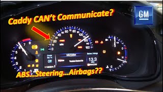
- U0077 on your Cadillac XTS is a critical network fault affecting safety systems like ABS and power steering.
- Do not drive the vehicle until it is repaired.
- The problem is most likely a broken or corroded wire under the driver's side floor trim, not an expensive module failure.
- Diagnosis is complex and requires professional tools; this is not a recommended DIY repair.
- Ensure your mechanic is aware of GM Technical Service Bulletin PIT5457C, as it directly addresses this common failure.
What's Unique About the 2013-2015 Cadillac XTS
For this generation of Cadillac and other GM Epsilon II platform vehicles, the U0077 code is frequently tied to specific, known wiring issues. Manufacturer Technical Service Bulletins (TSBs) like PIT5457D point directly to problems with the 'Communication Enable' circuit (5986) that can develop high resistance or an open circuit. The most common failure locations are in the wiring harness under the driver's or passenger's side sill plates and at a specific factory splice point (J365) under the passenger sill plate, which is prone to moisture and corrosion. This makes the problem more about specific, predictable wiring failure points than random module failures.
Diagnostic Flowchart
Tap your situation to follow the diagnostic path that matches what you're seeing on this vehicle.
Symptoms You May Notice
- Service ABS / Traction Control warning lights on the dash.
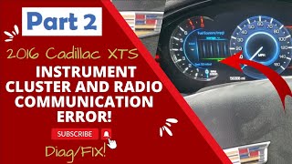
- Service Power Steering message displayed.
- Service Suspension System message displayed. 🎬 See how to diagnose GM ride control and suspension messages.
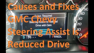
- Loss of power steering assist, making the wheel very hard to turn. 🎬 Watch: Common causes and fixes for GM steering assist reduced messages.
- ABS and StabiliTrak systems may be disabled.
- Backup camera may be inoperative or missing grid lines.
- Vehicle Settings icon on the infotainment screen may be grayed out.
- Replacing the Electronic Brake Control Module (EBCM) or Power Steering Control Module (PSCM) without first thoroughly checking the wiring harness. The modules themselves are less likely to fail than the wiring that connects them, especially Circuit 5986.
Most Likely Causes
- Wiring Harness Open/High Resistance/Short in Circuit 5986 🔴 High Probability GM TSBs PIT5457D and PIT5076E identify known failure points for the communication enable circuit (5986) and chassis bus wiring. These wires frequently corrode or break under the driver's side sill plate due to moisture ingress and foot traffic. Another documented failure point is Splice J365, located in the harness under the passenger's front sill plate, which is also prone to corrosion.
How to confirm: A technician will use a multimeter to check for voltage on the communication enable circuit (5986) at a non-communicating module (like the EBCM). Per TSB PIT5457D, this circuit should have ~12V with the key on. The TSB recommends load-testing the circuit with a small bulb (e.g., a 194 bulb) to ensure it can carry a small current; if the bulb doesn't light, an open or high resistance is present. They will also measure the resistance between pins 12 and 13 at the DLC, which should be 60 ohms, to test the integrity of the bus itself.
Typical fix: Locate the damaged section of the wiring harness, typically under the sill plates or carpeting, and repair the broken or corroded wire. This often involves splicing in a new section of wire and using heat-shrink tubing to protect the repair from future moisture. This is a labor-intensive but common fix.
Est. part cost: $5-$20 for wire and connectors - Low Battery Voltage or Poor Ground Connection 🟡 Medium Probability → Shop Vehicle Battery Modern control modules are sensitive to voltage and require stable grounds. A weak battery, loose terminal, or corroded ground strap can cause modules to fail their startup communication sequence, triggering network codes. GM has also issued TSBs (like 18-NA-161) regarding various electrical issues stemming from faulty main battery cables or ground connections.
How to confirm: Test the battery voltage with the vehicle off (should be ~12.6V) and running (should be ~13.7-14.7V). Load test the battery to confirm its health. Inspect main battery and chassis ground connections (e.g., G218 for the BCM) for cleanliness and tightness. Perform a voltage drop test on the main battery cables.
Typical fix: Recharge or replace the battery. Clean, tighten, or replace corroded or faulty ground straps or battery cables.
Est. part cost: $150-$300 for a new AGM battery - Failed Control Module ⚪ Low Probability While less common than wiring issues, any module on the Chassis Expansion Bus (EBCM, PSCM, SCM, etc.) can fail internally and bring down the entire network by shorting the communication lines or failing to terminate the bus.
How to confirm: This is a process of elimination. If the wiring (including Circuit 5986), power, and grounds are all confirmed to be good, a technician will use a scan tool to disconnect modules from the network one by one to see if communication is restored. The module whose disconnection restores the bus is the faulty one.
Typical fix: Replace the failed control module. The new module will require programming by a dealer or qualified shop with the correct GM software (SPS).
Est. part cost: $400-$1200 depending on the specific module
Rare But Worth Checking
- Pinched Instrument Panel (IP) Harness:
Diagnosis Steps
- Verify battery health and system voltage. Ensure the battery is fully charged (~12.6V) and terminals are clean.
- Connect a professional scan tool and attempt to communicate with all modules on the Chassis Expansion Bus (EBCM, PSCM, SCM). Note which modules are not responding.
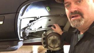
- Perform a visual inspection of the wiring harness, paying close attention to the areas under the driver's and passenger's side sill plates and carpeting, as noted in TSB PIT5457D. Look for signs of water intrusion or corrosion (white/green powder).
- Using a multimeter, check for approximately 12 volts on the Communication Enable circuit (Circuit 5986, often a yellow or purple wire) at the connector of a non-communicating module (e.g., the EBCM).
- If voltage is low/absent, perform a load test on Circuit 5986 as per TSB PIT5457D: connect a 194 bulb between the circuit and a good ground. If the bulb does not light brightly, trace Circuit 5986 back towards the BCM, inspecting for opens or high resistance, paying special attention to Splice J365 under the passenger sill plate.
- Measure the resistance across the Chassis Expansion Bus at the Data Link Connector (DLC), between pins 12 and 13. A healthy bus should read approximately 60 ohms.
- If resistance is incorrect (e.g., 120 ohms or open), it indicates a break in the bus wiring or a problem with one of the two terminating resistors (located within modules, often the EBCM and another module).
- If wiring, power, and grounds are confirmed good, the issue is likely a failed module. This is confirmed by disconnecting modules one by one until communication on the bus is restored.
Parts You'll Likely Need
- Wiring Harness Repair Supplies — The most common cause is a broken or corroded wire in the chassis harness, not a failed part.
Trusted brands: 3M, Delphi
OEM price range: $5-$20
Aftermarket price range: $5-$20 - Electronic Brake Control Module (EBCM)
(OEM #23131610, 22911900)— If a module has failed, the EBCM is one of the primary modules on this bus and can be a point of failure. This should only be replaced after exhaustive wiring diagnostics.
Trusted brands: ACDelco
OEM price range: $600-$900
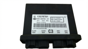
Aftermarket price range: $400-$700 (Remanufactured) - Body Control Module (BCM)
(OEM #13589093, 13586589)— The BCM provides the 'wake-up' signal on Circuit 5986. While a rare failure, a faulty BCM could fail to send this signal, causing the U0077 code.
Trusted brands: ACDelco
OEM price range: $300-$500
Aftermarket price range: $200-$400 (Programmed/Cloned)
Related Codes That Often Appear With This One
- U0121 — Lost Communication With Electronic Brake Control Module (EBCM).
- U0131 — Lost Communication With Power Steering Control Module (PSCM).
- U0126 — Lost Communication With Steering Angle Sensor Module.
- U0415 — Invalid Data Received From Electronic Brake Control Module.
- U0428 — Invalid Data Received From Steering Angle Sensor Module.
Technical Service Bulletins (TSBs) & Recalls
- PIT5076E: Instructs technicians to diagnose the Chassis bus when U0077 is present along with a list of other communication codes.
- PIT5457D: The most critical TSB for this issue. Details the failure of the Communication Enable circuit (5986) and points to specific harness locations under the sill plates and a splice (J365) as the most common culprits.
- PIT5288H: Relevant for related platforms, this TSB describes how a pinched instrument panel harness can cause U0077 and other communication failures.
Platform-Specific Known Issues
- TSB PIT5076E notes that U0077 can appear after other work is done and may require diagnosing the Chassis bus.
- TSB PIT5457D (which supersedes PIT5457C) specifically calls out high resistance or an open in the Communication Enable circuit (5986) as a cause for U0077. It identifies known problem areas under the driver's/passenger's sill plates and at Splice J365 under the passenger sill plate.
Mechanic-Grade Diagnostic Values
- Communication Enable Circuit (5986) Voltage — expected: Approximately 12V with key in ACC, ON, or START.. Failure: Low or no voltage indicates an open, short, or high resistance in the circuit.
- Communication Enable Circuit (5986) Load Test Voltage — expected: At least 11V measured across a 194-style light bulb connected between the circuit and ground.. Failure: If the bulb does not light, or the voltage across it is less than 11V, it indicates high resistance or an open circuit.
- Communication Enable Circuit (5986) Current Draw — expected: The circuit is low amperage; a 194 bulb draws approximately 250 mA (0.25A).. Failure: The BCM will shut down the circuit if the current draw exceeds 0.88 amps, which would happen in a short-to-ground scenario.
- BCM Ground (G218) Resistance — expected: Less than 5 mΩ (0.005 Ohms) to a clean chassis point.. Failure: Higher resistance indicates a poor ground connection, which can cause the BCM to malfunction.
Scan Tool Commands That Help
- GDS2 (Global Diagnostic System 2): Vehicle Communication Diagnostics > Network Communication Status — This is the first step to see a list of all CAN buses and identify which specific modules are not communicating, confirming the scope of the U0077 fault.
- GDS2 (Global Diagnostic System 2): Module Diagnostics > [Select Module] > Control Functions — After restoring communication, or to test a specific module, bidirectional controls (e.g., 'ABS Motor Test') can be used to verify the module is fully functional.
Wiring & Ground Locations
- Circuit 5986 — Runs from the BCM, down the driver's side A-pillar, under the driver's sill plate, across the vehicle to the passenger sill plate, and branches off to the EBCM, PSCM, and SCM.. This is the 'Communication Enable' or 'wake-up' circuit. An open, short, or high resistance in this wire is the most common cause of U0077.
- Splice J365 — Located in the wiring harness under the passenger's front door sill plate.. This is a known failure point where multiple branches of Circuit 5986 join. Corrosion or a bad connection here will cut off the wake-up signal to multiple modules.
- G218 — In the driver's footwell, near the base of the A-pillar, under the dash and potentially behind the kick panel.. This is a primary ground for the Body Control Module (BCM). A poor connection here can cause the BCM to malfunction and fail to send the wake-up signal on Circuit 5986.
- G305 — Located at the base of the left kick panel.. This is another ground point in the area of the BCM and instrument panel fuse block that is critical for data line communication.
- G103 — Located at the left rear of the engine compartment on the cowl, above the brake booster.. This is an alternative grounding point for the BCM, as well as the Instrument Panel Cluster (IPC) and Data Link Connector (DLC). A fault here could cause widespread communication issues.
- BCM Connector X5 — On the Body Control Module, which is located on the left front hinge pillar.. Circuit 5986 (Communication Enable) originates from a pin on this connector. A poor pin fit or corrosion here could be the source of the problem.
"I Checked Everything" — The Actual Cause
- In cases where wiring tests for continuity seem to pass, the actual cause can be a high-resistance ground connection at G218 (driver's footwell). From the factory, sound-deadening insulation can get trapped between the ground terminal and the chassis, leading to an intermittent and poor connection that is not a full open circuit but is enough to disrupt BCM function.
OEM Part Supersession History
13589093→13586589, 13580689— Standard part revision and consolidation by the manufacturer.
Heads up: These BCM part numbers are generally interchangeable for cloning/programming purposes, but you must verify the part number on your original module before ordering a replacement.
Helpful Videos
We Have This Part in Stock

The information in this article is provided for general reference and educational purposes only. Vehicle specifications, procedures, and part compatibility can vary by production date, trim level, and region. Always consult your vehicle's factory service manual and verify part numbers before purchasing or performing repairs. Safety-critical components such as airbags, seat belts, and braking systems should be installed by a qualified professional.
- Cadillac XTS:
- 🧭 Diagnostic Flowchart
- 🎬 Helpful Videos
- 🛍️ Shop This Part
- What's Unique About the 2013-2015 Cadillac XTS
- Symptoms You May Notice
- Most Likely Causes
- Rare But Worth Checking
- Diagnosis Steps
- Parts You'll Likely Need
- Related Codes That Often Appear With This One
- Technical Service Bulletins (TSBs) & Recalls
- Platform-Specific Known Issues
- Mechanic-Grade Diagnostic Values
- Scan Tool Commands That Help
- Wiring & Ground Locations
- "I Checked Everything" — The Actual Cause
- OEM Part Supersession History
- 🎟️ Get 5% Off