
U0077 on 2011-2015 Chevrolet Volt: Chassis Communication Bus Fault Guide
This code indicates a communication failure on the Chassis Expansion Bus, which connects critical safety modules. Symptoms often include 'Service Power Steering' and ABS/StabiliTrak warnings. The cause is frequently a wiring issue, a faulty Power Steering Control Module (PSCM), or a problem with the Electronic Brake Control Module (EBCM). Diagnosis is complex and often requires professional tools.
- U0077 on a 2011-2015 Volt is a serious network communication code that disables critical safety systems like power steering and ABS.
- Diagnosis is complex and should be performed by a professional with CAN bus diagnostic tools.
- Common causes are wiring/connector issues, a failed Power Steering Control Module (PSCM), or a failed Electronic Brake Control Module (EBCM).
- Before extensive diagnostics, always ensure the 12V AGM battery is fully charged and healthy, as low voltage can mimic network faults.
What's Unique About the 2011-2015 Chevrolet VOLT
The first-generation Chevrolet Volt has a complex electrical architecture with multiple data networks. The U0077 code specifically points to the Chassis Expansion Bus, which was added to run in parallel with the primary high-speed network to reduce data traffic. Because this bus serves critical components like electric power steering and electronic brakes, a failure can lead to immediate and noticeable drivability issues. Unlike some vehicles where a similar code might only affect convenience features, on the Volt, it directly impacts primary vehicle control systems. The Cadillac ELR, built on the same platform, can experience similar failures.
Diagnostic Flowchart
Tap your situation to follow the diagnostic path that matches what you're seeing on this vehicle.
Symptoms You May Notice
- "Service Power Steering" message on the dashboard.
- Loss of or difficult power steering.
- ABS and/or Traction Control (StabiliTrak) warning lights illuminated.
- Multiple warning lights appearing simultaneously.
- The vehicle may fail to enter a reduced power mode.
- "Service High Voltage Charging System" message in some cases where multiple communication buses are affected.
- Replacing the Body Control Module (BCM) without proper diagnosis. While the BCM acts as a gateway, the U0077 code on a Volt specifically points to the Chassis Expansion Bus, not a BCM failure itself. The BCM may log codes due to the fault, but it is rarely the cause of U0077.
Most Likely Causes
- Wiring Harness or Connector Failure 🔴 High Probability Connectors and wiring for chassis components are exposed to the elements, increasing the risk of corrosion, water intrusion, or physical damage from road debris. A single bad connection, short-to-ground, or open circuit in the twisted pair of CAN wires can take down the entire network.
How to confirm: Visually inspect the wiring harnesses and connectors going to the Power Steering Control Module (PSCM) and Electronic Brake Control Module (EBCM) for any signs of corrosion, damage, or loose pins. A multimeter can be used to check for approximately 60 ohms of resistance between pins 12 and 13 of the DLC, which confirms the integrity of the two main terminating resistors on the bus. A reading of 120 ohms suggests one terminating module is offline; a reading near zero ohms indicates a short circuit.
Typical fix: Repair the damaged section of the wiring harness or clean/replace the corroded connector. Applying dielectric grease can help prevent future corrosion.
Est. part cost: $10-$100 - Failed Power Steering Control Module (PSCM) 🟡 Medium Probability → Shop Power Steering Control Module The PSCM is a primary module on the chassis bus. An internal failure within this module can cause it to stop communicating or, in some cases, 'shout' on the network with garbage data, preventing other modules from communicating. In at least one documented case, a new PSCM fixed an open in the CAN bus and resolved the issue.
How to confirm: After verifying the wiring is intact, a diagnostic scan tool can be used to see if the PSCM is responsive. A common diagnostic step is to disconnect the PSCM connector and see if communication with other modules on the bus is restored. If it is, the PSCM is the likely culprit.
Typical fix: Replace the Power Steering Control Module, which is often integrated into the power steering rack assembly. This repair is labor-intensive and requires programming to the vehicle.
Est. part cost: $400-$1000 - Failed Electronic Brake Control Module (EBCM) 🟡 Medium Probability → Shop ABS Control Module The EBCM is another critical node on the chassis bus and contains one of the network's 120-ohm terminating resistors. An internal fault can bring down the entire network, causing the U0077 code along with ABS and Stabilitrak warnings.
How to confirm: Check for power and ground at the EBCM. Disconnect the module and re-check the bus resistance at the DLC. If the resistance changes significantly (e.g., from 120 ohms to open, or 60 ohms to 120 ohms), or if communication is restored with the EBCM disconnected, the module is likely faulty.
Typical fix: Replace the Electronic Brake Control Module. This part requires programming with GM's SPS2 software and a brake bleed procedure.
Est. part cost: $300-$800 - Weak or Failing 12V Battery ⚪ Low Probability → Shop Vehicle Battery Like many modern cars, the Volt is extremely sensitive to low voltage. A weak 12V AGM battery can cause random communication codes and module glitches as systems power up, sometimes before a 'Service Battery' warning appears. A stable 12V source is also critical for any module reprogramming.
How to confirm: Test the 12V AGM battery with a proper electronic load tester. Voltage should be approximately 12.6V when the car is off and 13.7-14.7V when the car is in 'Ready' mode.
Typical fix: Replace the 12V AGM battery.
Est. part cost: $180-$300
Rare But Worth Checking
- Failure of another module on the Chassis Bus: While less common, other modules like the Suspension Control Module (if equipped) or Chassis Control Module could also fail and disrupt the network. Diagnosis involves unplugging modules one by one to isolate the fault.
- Faulty Diagnostic Link Connector (DLC): TSB #PIT5076E suggests that if codes cannot be cleared after a repair, the issue may lie with the diagnostic tool's connection to the DLC, implying a potential issue with the port itself.
Diagnosis Steps
- Connect a professional scan tool capable of reading all vehicle modules. Check for codes in the EBCM, PSCM, BCM, and other relevant modules. Note which modules are not communicating.
- Check the 12V battery's state of health and charge. A weak battery can cause numerous communication faults. Ensure voltage is stable before proceeding.
- Perform a thorough visual inspection of the wiring harnesses to the EBCM and PSCM. Look for any signs of physical damage, chafing, or corrosion at the connectors.
- With the ignition off and 12V battery disconnected, measure the resistance between Pin 12 (CAN High) and Pin 13 (CAN Low) on the Data Link Connector (DLC). A reading of approximately 60 ohms indicates the bus wiring and the two 120-ohm terminating resistors are likely intact. A reading of 120 ohms suggests one of the terminating modules (like the EBCM) is offline or the wiring to it is broken. A reading near zero ohms indicates a short circuit between the two CAN wires.
- If the resistance is incorrect (120 ohms or an open circuit), begin disconnecting modules on the Chassis Expansion Bus one at a time (PSCM, EBCM, etc.) and re-measure the resistance each time. When the resistance returns to a normal value (e.g., from open to 120 ohms after unplugging the EBCM), the last module disconnected is the likely source of the fault.
- If a specific module is suspected, verify it is receiving proper power and has a clean ground connection before condemning the module.
- If wiring and modules appear to be good, check for Technical Service Bulletins (TSBs) related to this code. TSB #PIT5076E specifically mentions diagnosing the chassis bus for this code and related faults.
Parts You'll Likely Need
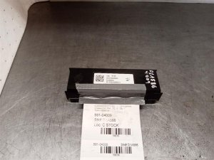
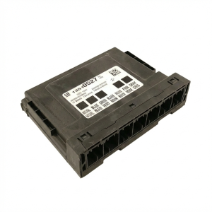
- Power Steering Control Module / Steering Rack Assembly — This module is a frequent point of failure that can bring down the entire chassis communication bus. On the Volt, the control module is typically serviced as part of the complete power steering rack assembly.
Trusted brands: ACDelco (GM Genuine)
OEM price range: $600-$1000
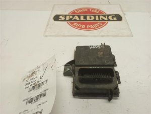
Aftermarket price range: $400-$700 (Remanufactured) - Electronic Brake Control Module (EBCM) — As a terminating module on the bus, an internal failure in the EBCM will cause a U0077 code and ABS/StabiliTrak warnings. Part number must be verified with the vehicle's VIN.
Trusted brands: ACDelco (GM Genuine)
OEM price range: $500-$800
Aftermarket price range: $300-$600 (Remanufactured) - Wiring Harness Pigtail / Connector — Corrosion or damage to the connectors for the PSCM or EBCM is a common cause of this fault. Sometimes only the connector end (pigtail) needs to be replaced, not the entire harness.
Trusted brands: ACDelco, Dorman
OEM price range: $40-$100
Aftermarket price range: $20-$60
Related Codes That Often Appear With This One
- U0121 — Lost Communication With Electronic Brake Control Module (EBCM)
- U0131 — Lost Communication With Power Steering Control Module (PSCM)
- U0074 — Control Module Communication Bus B Off (another bus communication code)
- C0186, C0196, C0287 — These are chassis-related codes that may be set in conjunction with the communication fault, as mentioned in TSB #PIT5076E.
- U0125, U0126 — Lost communication with the Multi-axis Acceleration Sensor Module or Steering Angle Sensor module, which are also on the chassis bus.
Technical Service Bulletins (TSBs) & Recalls
- Advises on diagnosing the Chassis Bus when U0077 and other codes are present and will not clear, and suggests checking the diagnostic interface itself.
Platform-Specific Known Issues
- TSB PIT5076E - Diagnostic Guidance: This bulletin notes that if a U0077 code is present and will not clear after other repairs (like a steering angle sensor learn), the technician should diagnose the Chassis bus directly. It also suggests that if no fault is found, the diagnostic tool interface itself could be the problem, and a different diagnostic cable should be tried.
- Real-World Repair: PSCM Failure: A documented repair on the ScannerDanner forum for a 2011 Volt showed that after extensive diagnosis, a new Power Steering Control Module fixed an open in the CAN bus, resolving communication issues. This confirms the PSCM as a key point of failure.
Mechanic-Grade Diagnostic Values
- Chassis Expansion CAN Bus Voltage (Key On) — expected: Both CAN High (Pin 12) and CAN Low (Pin 13) should idle at ~2.5V. During data transmission, High should pulse to ~3.5V and Low should drop to ~1.5V.. Failure: A flat line, voltage stuck high or low, or noisy signals indicate a bus problem. A short to ground will show 0V; a short to power will show >5V or 12V.
- Communication Enable Circuit Voltage — expected: Approximately 12 volts when the BCM is awake (e.g., key on or accessory mode).. Failure: Low or no voltage suggests a problem with the 'wake-up' signal from the BCM, preventing chassis modules from activating.
- Module Ground Resistance — expected: Less than 5 milliohms (mΩ) between the module's ground pin and a clean chassis ground.. Failure: High resistance indicates a poor ground connection, which can cause unpredictable module behavior and communication errors.
Hidden / Shadow Codes Worth Checking
- U0077 with Symptom Byte (e.g., 71): The authoritative TSB #PIT5076E mentions 'symptom code 71' can be set in the EBCM or PSCM along with U0077. While the specific meaning of '71' is not publicly defined, its presence indicates that the dealer-level scan tool has more granular information about the nature of the communication fault (e.g., which module initiated the fault). (see via GM GDS2 (Global Diagnostic System 2) or equivalent high-end professional scan tool.)
Scan Tool Commands That Help
- GM GDS2: Module Communication Status / Talk-back Test — After confirming U0077 is active, this function is used to 'ping' each module on the Chassis Expansion Bus. It helps identify exactly which module(s) are not responding, narrowing the search to that module and its specific wiring.
- GM GDS2: SPS (Service Programming System) — This function is mandatory after replacing a major control module like the EBCM or PSCM. It loads the correct vehicle-specific software and VIN into the new module, allowing it to communicate on the network.
Wiring & Ground Locations
- DLC Pins 12 & 13 — On the 16-pin OBD-II Data Link Connector (DLC) under the driver's side dashboard.. These are the direct test points for the Chassis Expansion Bus. Pin 12 is CAN High and Pin 13 is CAN Low. All primary electrical diagnostics (resistance, voltage, oscilloscope) for this network start here.
- EBCM Connector — On the Electronic Brake Control Module, typically part of the ABS pump assembly in the engine bay.. This connector is a critical junction. The EBCM contains a terminating resistor for the bus. A loose pin, corrosion, or damage here can cause an open circuit (120-ohm reading) and bring the network down.
- PSCM Connector — On the Power Steering Control Module, which is typically mounted on the power steering rack itself, under the vehicle.. This is another primary module on the bus. The connector is exposed to road debris and moisture, making it a potential point of failure for wiring or corrosion issues.
Real Owner Repair Stories
- YouTube channel 'Automotive Diagnostics & Programming' (similar GM K2XX platform) (2019 Chevrolet Tahoe) — Multiple communication codes including U0077, no communication with EBCM and other chassis modules.
❌ Tried (didn't work) Initial diagnosis pointed towards a bad module because the bus resistance showed 120 ohms, indicating an open circuit.
✅ What actually fixed it An intermittent connection was found by wiggling the EBCM connector. The root cause was a single loose female pin inside the EBCM connector. The pin was removed and tightened, restoring the connection and resolving the fault without replacing any parts. - CorvetteForum user discussion (2017 Chevrolet Corvette Z06) — Persistent U0077 code that would not clear.
❌ Tried (didn't work) Clearing the code with a standard scan tool.
✅ What actually fixed it The user was advised that modules can miss their 'handshake' window during vehicle startup, especially after a battery disconnect. The suggested, non-standard fix was to disconnect the battery for a few minutes and reconnect it, sometimes multiple times. This can force all modules to re-initialize properly on the network.
"I Checked Everything" — The Actual Cause
- The diagnostic equivalent for CAN bus is a resistance test. A common dead-end is when the bus resistance measures a perfect 60 ohms, suggesting the wiring is fine, yet communication is still down. This can happen if a module is 'shouting' garbage data onto the bus, disrupting other modules without creating an electrical short or open. Another scenario, documented on a similar GM platform, was a loose pin in the EBCM connector that only lost contact intermittently with vibration, causing a U0077 code but potentially testing fine when static.
OEM Part Supersession History
22935892→N/A (See note)— This is the specified part number for the EBCM on early models.
Heads up: According to GM bulletin PIC5383D, this part, along with the 2014 version, was placed on restriction, requiring dealers to contact the Technical Assistance Center (TAC) to review diagnostics before ordering. This suggests a high rate of misdiagnosis or a need to track failures.23154359→N/A (See note)— This is the specified part number for the EBCM on later models.
Heads up: This part number applies specifically to the 2014 Volt and was also placed on restriction by GM, per bulletin PIC5383D. Using the wrong year's module will likely result in failure to program or communicate.
Model Year Variations Within This Range
- 2011-2013 vs 2014: The Electronic Brake Control Module (EBCM) has a different part number for 2014 models (23154359) compared to 2011-2013 models (22935892), indicating an internal change. These parts are not interchangeable.
Helpful Videos
We Have This Part in Stock

The information in this article is provided for general reference and educational purposes only. Vehicle specifications, procedures, and part compatibility can vary by production date, trim level, and region. Always consult your vehicle's factory service manual and verify part numbers before purchasing or performing repairs. Safety-critical components such as airbags, seat belts, and braking systems should be installed by a qualified professional.
- Chevrolet VOLT:
- 🧭 Diagnostic Flowchart
- 🎬 Helpful Videos
- 🛍️ Shop This Part
- What's Unique About the 2011-2015 Chevrolet VOLT
- Symptoms You May Notice
- Most Likely Causes
- Rare But Worth Checking
- Diagnosis Steps
- Parts You'll Likely Need
- Related Codes That Often Appear With This One
- Technical Service Bulletins (TSBs) & Recalls
- Platform-Specific Known Issues
- Mechanic-Grade Diagnostic Values
- Hidden / Shadow Codes Worth Checking
- Scan Tool Commands That Help
- Wiring & Ground Locations
- Real Owner Repair Stories
- "I Checked Everything" — The Actual Cause
- OEM Part Supersession History
- Model Year Variations Within This Range
- 🎟️ Get 5% Off