
U0077 on 2015-2020 GMC Yukon XL: Chassis Bus Communication Failure Causes & Fixes
On a 2015-2020 GMC Yukon XL, code U0077 almost always points to a communication failure on the chassis CAN bus. This is most frequently caused by a pinched or damaged wiring harness, particularly under the driver/passenger sill plates or behind the instrument panel, as documented in GM TSBs. The fix is to locate and repair the compromised wires, which are often the Tan and Tan/Black CAN bus pair.
- U0077 on a 2015-2020 Yukon XL is a serious network code, not a simple sensor fault.
- Do not drive the vehicle. A loss of communication with steering and brake modules is a major safety risk.
- The most likely cause is a damaged wire. Always inspect the harnesses under the sill plates and behind the dash before considering module replacement.
- This is a complex electrical issue that is best left to a professional technician with experience in CAN bus diagnostics.
What's Unique About the 2015-2020 Gmc YUKON XL

The K2XX platform, which includes the 2015-2020 GMC Yukon XL, is well-documented by GM to have specific vulnerabilities in its wiring harness routing. Multiple Technical Service Bulletins (TSBs), such as PIT5457 and PIT5288H, have been issued that point technicians directly to common chafe points and areas where harnesses can be pinched. This is not a random electrical fault; it's a known pattern of failure for this specific vehicle generation, making a wiring inspection the primary diagnostic step before replacing any modules.
Diagnostic Flowchart

Tap your situation to follow the diagnostic path that matches what you're seeing on this vehicle.
Symptoms You May Notice

- "Service Power Steering System" message on the dash
- "Service Suspension System" message (for vehicles with magnetic ride control).
- "Service ABS", "Service Traction Control", or "Service Stabilitrak" warnings.
- Loss of power steering assist, making the wheel very hard to turn.
- Instrument cluster gauges behaving erratically or going dark
- Vehicle may not start (no crank condition).
- Dead battery due to modules not going to 'sleep'.
- Radio or infotainment screen going blank intermittently.
- Erratic behavior of door locks or windows.
- Replacing the Electronic Brake Control Module (EBCM) or Power Steering Control Module (PSCM) without first performing a thorough inspection of the wiring harness. The harness is the most common point of failure for this code on this platform, as confirmed by multiple TSBs and owner forums.
Most Likely Causes

- Damaged or Pinched Wiring Harness 🔴 High Probability As documented in GM TSBs #PIT5457 and #PIT5288H, the wiring harness for the chassis CAN bus is routed in areas where it is susceptible to damage. Common failure points are under the driver and passenger door sill plates and behind the left side of the instrument panel where the harness can be pinched by a dash mounting bracket.
How to confirm: Perform a thorough visual inspection of the harness in the locations specified by the TSBs. Look for chafed insulation, pinched wires, or signs of corrosion. The Chassis CAN bus wires are typically a twisted pair of Tan and Tan/Black wires. A multimeter can be used to check for continuity and shorts to ground on these wires. You can also check resistance between pins 12 and 13 of the OBD-II port (Chassis CAN Bus). A healthy bus should read approximately 60 ohms. A reading of 120 ohms suggests an open circuit, while a reading near 0 ohms indicates a short circuit.
Typical fix: Carefully repair the broken or shorted wires using solder and heat shrink or appropriate sealed connectors. Reroute the harness slightly if possible to prevent future damage. TSB #PIT5288H specifically advises to free the harness from the pinch point and then repair the wires.
Est. part cost: $10-$50 - Faulty Control Module 🟡 Medium Probability An internal failure in any module on the chassis bus (e.g., EBCM, PSCM, SCM, or Airbag Module) can cause it to short out the entire network, bringing communication to a halt. The EBCM and Airbag Module often contain the two 120-ohm terminating resistors for the bus.
How to confirm: If the wiring harness inspection reveals no faults, the next step is to isolate the bad module. This is done by unplugging modules on the chassis bus one by one. When the faulty module is disconnected, communication between the remaining modules should be restored (the 60-ohm resistance reading should return). This requires a scan tool that can monitor network status in real-time and knowledge of module locations.
Typical fix: Replace the failed module. The new module will require programming by a dealer or a qualified shop with the correct software (e.g., GM MDI with GDS2).
Est. part cost: $400-$1200 - Poor Connection or Corrosion ⚪ Low Probability Connectors, especially those exposed to the elements under the vehicle (like at the EBCM), can develop corrosion. Connectors behind kick panels or under sill plates can be damaged by water intrusion from clogged sunroof drains or weather seals.
How to confirm: Visually inspect the main connectors for the EBCM, PSCM, and SCM. Look for green or white corrosion on the pins, or any signs of water entry. Wiggle-testing connectors while monitoring the bus with a scope or scan tool can also reveal a poor connection.
Typical fix: Clean the corroded terminals with a specialized contact cleaner or replace the connector pigtail and damaged pins.
Est. part cost: $20-$100
Rare But Worth Checking
- High Resistance in Battery Cables or Poor Grounds: → Shop Vehicle Battery
Diagnosis Steps
- Connect a professional scan tool and perform a full vehicle DTC scan. Note all modules that are reporting 'No Communication' on the Chassis CAN bus.
- Confirm the battery is fully charged and the terminals are clean and tight. Perform a load test on the battery. Low or unstable voltage is a known cause of communication faults.
- Based on TSB #PIT5457, remove the driver and passenger front sill plates and inspect the wiring harness that runs along the floor. Look specifically for the twisted pair of Tan and Tan/Black wires for any signs of chafing, pinching, or corrosion.
- Based on TSB #PIT5288H, inspect the wiring harness behind the left side of the instrument panel, near the dash mounting bracket, for a pinch point.
- If no visible damage is found, disconnect the battery. Use a multimeter to check the resistance between pin 12 (CAN-High) and pin 13 (CAN-Low) of the OBD-II port. A healthy bus should read approximately 60 ohms. A reading of 120 ohms suggests an open in the circuit or a missing termination resistor. A reading near 0 ohms indicates a short between the two wires.
- If the resistance is incorrect, begin disconnecting modules on the chassis bus one at a time (EBCM, PSCM, SCM, Airbag Module) while monitoring the resistance. If the reading corrects to 120 ohms after unplugging a specific module, that module is likely shorted internally.
- If you have an open circuit (120 ohms), check resistance from each end of the harness towards the middle to pinpoint the break.
- Once the fault (wiring or module) is identified, perform the necessary repair or replacement.
- Clear all DTCs and perform a test drive to ensure the issue is resolved and no warning lights return.
Parts You'll Likely Need
- Wiring Harness Repair Supplies — This is the most common fix, as the issue is frequently a broken or shorted wire in the chassis CAN bus harness.
Trusted brands: 3M, Delphi
OEM price range: $10-$50
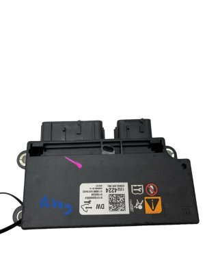
Aftermarket price range: $10-$50 - Electronic Brake Control Module (EBCM)
(OEM #84423329 (example, verify with VIN))— If a module is found to be at fault, the EBCM is a possibility. It contains a termination resistor for the bus and is a critical safety component.
Trusted brands: ACDelco
OEM price range: $500-$900
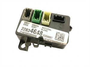
Aftermarket price range: $300-$600 - Power Steering Control Module (PSCM)
(OEM #23382581 (example, verify with VIN))— Another common module on the chassis bus that can fail and bring down the network, directly causing the 'Service Power Steering' message.
Trusted brands: ACDelco
OEM price range: $400-$700
Related Codes That Often Appear With This One
- U0121 — Lost Communication With Electronic Brake Control Module (EBCM)
- U0126 — Lost Communication With Steering Wheel Angle Sensor Module
- U0131 — Lost Communication With Power Steering Control Module (PSCM)
- U0415 — Invalid Data Received From Electronic Brake Control Module
- U0151 — Lost Communication With Inflatable Restraint Sensing and Diagnostic Module
Technical Service Bulletins (TSBs) & Recalls
- PIT5288H: Addresses a no-crank/no-start or dead battery condition caused by a pinched wire harness in the left instrument panel.
- PIT5457B: Pertains to various service messages (ABS, Power Steering, Suspension) caused by an open or high resistance in the communication enable circuit (5986) under the sill plates or near the spare tire crossmember.
- PIT5076E: Confirms that U0077 relates specifically to the Chassis bus and should be the focus of diagnosis.
- 18-NA-161: Details how high resistance in battery cables or poor grounds can cause voltage drops, leading to loss of power steering and communication DTCs like U0077.
Platform-Specific Known Issues
- TSB #PIT5457B specifically calls out high resistance in the 'Communication Enable circuit 5986' under the driver's or passenger's sill plate area, leading to loss of communication with the EBCM, PSCM, and SCM.
- TSB #PIT5288H points to a pinched wire harness on the left side of the instrument panel by a metal bracket as a cause for a no-start condition accompanied by code U0077 and other communication DTCs.
- TSB #PIT5076E instructs technicians to diagnose the Chassis bus when U0077 is present and will not clear, confirming the code's link to this specific network.
- On short wheelbase utilities (Tahoe, Yukon), TSB #PIT5457B also mentions the chassis harness can be cut or pinched between the body and the spare tire crossmember.
Mechanic-Grade Diagnostic Values
- Chassis CAN Bus Resistance — expected: ~60 Ω (measured between pins 12 & 13 of DLC with battery disconnected). Failure: 120 Ω indicates an open circuit or one missing terminating resistor. ~0 Ω indicates a short between CAN High and Low wires. 40 Ω or less could indicate a third, unwanted resistor on the network or a shorted module.
- CAN Bus Voltage (Key On, Engine Off) — expected: CAN High (Pin 12) and CAN Low (Pin 13) should both idle around 2.5V relative to ground. During active communication, CAN High pulses to ~3.5V and CAN Low pulses to ~1.5V.. Failure: Voltages stuck high or low, or one line showing no activity, indicates a short to power/ground or a faulty module/wiring. Measuring with a standard multimeter may show averaged, seemingly random values; an oscilloscope is required for accurate waveform analysis.
- Communication Enable Circuit (5986) Voltage — expected: Should have battery voltage when the ignition is in ACC, ON, or START. The BCM supplies this voltage to 'wake up' modules on the chassis bus.. Failure: Low or no voltage on this circuit will prevent modules from communicating, even if the CAN bus wiring is intact. TSB PIT5457D warns that loading this circuit with more than ~0.88 amps (like a large test light) can cause the BCM to shut the circuit down, leading to misdiagnosis.
Hidden / Shadow Codes Worth Checking
- History vs. Current DTC Status: A critical diagnostic clue is whether the U0077 code is listed as 'current' or 'history'. A history code indicates the fault occurred in the past but is not presently active, suggesting an intermittent connection or a resolved issue. A current code indicates the fault is happening now. (see via This status is visible on professional scan tools, including the dealer-level GM GDS2 software.)
Scan Tool Commands That Help
- GM GDS2 (Global Diagnostic System 2): Data Bus Diagnostic Tool — This function is used to get a live overview of all control modules on the network. It shows which modules are communicating and which are not, helping to quickly identify the scope of the communication failure and providing a starting point for diagnosis.
- GM GDS2 (Global Diagnostic System 2): Module Status / DTC Display — Used to read all DTCs from all modules. For a U0077, this is critical to see which other modules are logging 'lost communication' codes, which helps map out the fault. It also shows the 'current' or 'history' status of the code.
Wiring & Ground Locations

- Chassis Expansion Bus Terminating Resistors — The two 120-ohm terminating resistors are located internally within the Electronic Brake Control Module (EBCM) and the Inflatable Restraint Sensing and Diagnostic Module (Airbag Module).. A resistance reading of 120 ohms at the DLC points to a break in the wiring between the two terminating resistors or a failure of one of these modules. Knowing their location is key to sectionalizing the circuit for diagnosis.
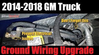
- G218 — A critical body ground located on the driver's side A-pillar, behind the plastic kick panel and under the dash.. This is the main ground for the Body Control Module (BCM). TSBs and repair stories confirm that sound-deadening insulation often gets trapped between the ground terminal and the body, causing high resistance. This can lead to voltage drops that cause multiple modules to malfunction and drop off the network, setting a U0077.
- Splice J365 — Located in the wiring harness under the passenger's front door sill plate.. TSB PIT5457D identifies this splice as a known failure point for the Communication Enable Circuit (5986). A corroded or broken splice here can prevent modules from waking up, causing a U0077 code.
- Chassis CAN Bus at DLC — Pins 12 (CAN High, Tan/Black wire) and 13 (CAN Low, Tan wire) on the vehicle's OBD-II Data Link Connector (DLC).. This is the most accessible point to perform initial network-wide resistance and voltage checks without disassembling any part of the vehicle.
Real Owner Repair Stories
- gm-trucks.com & tahoeyukonforum.com user experiences (Multiple 2015-2018 GMC Sierra / Chevy Silverado trucks (K2XX Platform)) — Service Stabilitrak, Service Power Steering, ABS light, and a cluster of U-codes including U0077.
❌ Tried (didn't work) Replacing battery, replacing modules like PSCM or EBCM.
✅ What actually fixed it In many documented cases, the final fix was locating and repairing a chafed or broken wire in the harness that runs under the driver's side door sill plate. The tan and tan/black wires were frequently the culprits. - YouTube Repair Channel 'Car Justify' (Chevy Silverado (K2XX Platform)) — Service StabiliTrak light, truck goes into limp mode.
❌ Tried (didn't work) Shop quoting steering angle sensor or throttle body replacement.
✅ What actually fixed it Cleaning a corroded frame ground wire located under the driver's side door area. The video explains that a weak ground causes voltage instability that the sensitive StabiliTrak system interprets as a major fault. - CorvetteForum user discussion (2017 Chevrolet Corvette Z06 (similar GM CAN architecture)) — Persistent U0077 code after fixing a known battery ground issue.
❌ Tried (didn't work) Clearing the code with a scan tool.
✅ What actually fixed it Disconnecting the battery for 2-5 minutes and reconnecting, then starting the vehicle. This was done 2-3 times. The theory is that after a power interruption, a module can miss its 'handshake' window during boot-up. A full power cycle forces all modules to re-initialize on the network, which can clear a persistent communication code if no hard fault exists.
"I Checked Everything" — The Actual Cause
- The electrical equivalent is when the CAN bus wiring (the Tan and Tan/Black wires) passes continuity and resistance checks perfectly, yet the U0077 code persists. In these cases, the root cause is often not the bus wiring itself, but the power or ground supplying the modules on the bus. A poor ground at G218 or high resistance in a main battery cable can cause intermittent voltage drops under load (like when turning the steering wheel), making modules temporarily drop off the network and trigger the code.
Model Year Variations Within This Range
- 2015-2019: While the fundamental issue remains the same, GM Technical Service Bulletin PIT5457 was updated multiple times to expand the model years covered, with version 'D' being released in June 2019 to officially include the 2019 model year, confirming the wiring harness chafe points are a persistent issue across this range.
Helpful Videos
We Have This Part in Stock

The information in this article is provided for general reference and educational purposes only. Vehicle specifications, procedures, and part compatibility can vary by production date, trim level, and region. Always consult your vehicle's factory service manual and verify part numbers before purchasing or performing repairs. Safety-critical components such as airbags, seat belts, and braking systems should be installed by a qualified professional.
- Gmc YUKON XL:
- 🧭 Diagnostic Flowchart
- 🎬 Helpful Videos
- 🛍️ Shop This Part
- What's Unique About the 2015-2020 Gmc YUKON XL
- Symptoms You May Notice
- Most Likely Causes
- Rare But Worth Checking
- Diagnosis Steps
- Parts You'll Likely Need
- Related Codes That Often Appear With This One
- Technical Service Bulletins (TSBs) & Recalls
- Platform-Specific Known Issues
- Mechanic-Grade Diagnostic Values
- Hidden / Shadow Codes Worth Checking
- Scan Tool Commands That Help
- Wiring & Ground Locations
- Real Owner Repair Stories
- "I Checked Everything" — The Actual Cause
- Model Year Variations Within This Range
- 🎟️ Get 5% Off