
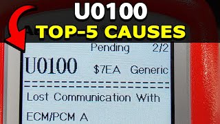
U0100 on 2004-2011 Cadillac CTS: Causes and Fixes for Lost Communication
U0100 on a 2004-2011 Cadillac CTS almost always indicates a wiring problem, not a failed computer. For 2008-2011 models, check the transmission X1 connector for loose pins per TSB #PIC4740E. For 2004-2007 models, inspect the ECM power (CKT 5290) and Class 2 data line (CKT 1807) wiring per TSB #PIC5460B. This is a complex electrical issue, and professional diagnosis is recommended before replacing expensive modules.
- U0100 on a 2004-2011 CTS is a critical fault that makes the vehicle unsafe to drive.
- The cause is almost certainly a wiring issue, not a bad ECM. Do not replace the ECM without exhaustive testing.
- For 2008-2011 models, the first place to look is the transmission harness connector (X1).
- For 2004-2007 models, inspect the wiring harness leading to the ECM for power and data line faults.
- Due to the complexity of network diagnostics, professional service is highly recommended.
What's Unique About the 2004-2011 Cadillac CTS

The 2004-2011 Cadillac CTS spans two distinct generations built on the GM Sigma platform, and both have documented, specific wiring vulnerabilities that cause the U0100 code. Unlike many vehicles where this code might lead to immediately suspecting the ECM, on the CTS, the problem is very frequently a wiring fault identified in official GM Technical Service Bulletins. For the second generation (2008-2011), the transmission harness connector is a known weak point. For the first generation (2004-2007), power or data wiring to the ECM is a more common culprit. This makes a wiring-first diagnostic approach essential.
🎬 Watch: Common causes and fixes for the U0100 codeDiagnostic Flowchart

Tap your situation to follow the diagnostic path that matches what you're seeing on this vehicle.
Generation note: This guide covers the first generation (2004-2007) and the second generation (2008-2011) of the Cadillac CTS. The primary causes differ between them. TSB #PIC5460B applies mainly to the first generation, pointing to the ECM's Ignition 1 Power Feed (Circuit 5290) or the Class 2 data line (Circuit 1807). TSB #PIC4740E applies to the second generation, identifying the transmission X1 connector as a common failure point causing loss of communication with the ECM and TCM.
Symptoms You May Notice

- Check Engine Light is on (or may flicker/not illuminate at all)
- Vehicle will not crank or start
- Engine may stall while driving
- Transmission shifts hard or gets stuck in one gear (limp mode)
- Multiple warning lights on the dashboard (StabiliTrak, ABS, Traction Control, etc.)
- Loss of power or vehicle enters "limp mode"
- Erratic gauge behavior or all gauges drop to zero
- Key may get stuck in the ignition after a failed start attempt
- "Service Stabilitrak" or "Service Traction Control" message on the DIC
- Replacing the Engine Control Module (ECM) without first performing a thorough diagnosis of the wiring harness, power feeds, and ground connections. The TSBs for this vehicle strongly suggest wiring is the primary culprit.
Most Likely Causes

- Loose or Damaged Pins in Transmission X1 Connector 🔴 High Probability → Shop Transmission Assembly This is a well-documented issue for 2nd generation (2008-2011) models, as cited in GM TSB #PIC4740E. The pins for the GMLAN serial data lines that pass through this connector can become unseated or corroded, causing intermittent loss of communication between the TCM and ECM.
How to confirm: Locate and disconnect the large X1 connector at the transmission. Visually inspect for corrosion or damage. Gently tug on each wire in the connector to ensure the terminals are fully seated and locked in place. A side load on the wires may cause a false positive lock, so be thorough.
Typical fix: Reseat any loose terminals. Clean any corrosion with electrical contact cleaner. If the connector, terminals, or seals are damaged, they may need to be replaced with a pigtail kit.
Est. part cost: $5-$75 - Wiring Fault in ECM Power or Data Circuit 🔴 High Probability For 1st generation (2004-2007) models, TSB #PIC5460B points to issues with the Ignition 1 Power Feed (Circuit 5290) or the Class 2 data line (Circuit 1807) wiring to the ECM. Chafing or corrosion can interrupt the signal, causing a no-crank condition and U0100 in other modules.
How to confirm: Visually inspect the wiring harness leading to the ECM for any signs of damage, chafing against brackets, or corrosion. Use a multimeter and a wiring diagram to check for battery voltage at the ECM fuse in the underhood fuse block and on Circuit 5290 at the ECM connector. Check for continuity on the Class 2 data line (Circuit 1807) between the ECM and the data link connector.
Typical fix: Repair the damaged section of the wiring harness. This may involve soldering, splicing, and protecting the repaired area with heat shrink tubing and loom.
Est. part cost: $1-$20 - Low Battery Voltage or Poor Ground Connection 🟡 Medium Probability → Shop Vehicle Battery All modern vehicles are sensitive to low voltage, which can cause control modules to randomly drop off the communication network. A poor ground connection at a key point, like the main engine block ground (G101), can prevent the ECM from powering up correctly.
How to confirm: Test the battery with a multimeter; it should read at least 12.4V with the engine off and above 13.5V with the engine running. Check and clean the main battery terminals, engine ground strap (G101, engine block to chassis), and main chassis ground points for tightness and corrosion.
Typical fix: Charge or replace the battery. Replace the alternator if not charging correctly. Clean or tighten all ground connections.
Est. part cost: $0-$450
Rare But Worth Checking
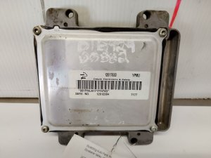
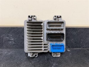
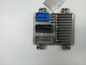
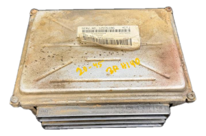
- Failed Engine Control Module (ECM): → Shop Engine Control Module (ECM) This is the most commonly misdiagnosed cause. The ECM should only be suspected after all wiring, power, and ground issues have been completely ruled out. However, in rare cases, the ECM can fail internally due to component failure on the circuit board.
- Faulty Terminating Resistor: The CAN bus network (GMLAN on Gen 2) has two 120-ohm terminating resistors, one inside the ECM and one inside the BCM. If one fails or a wiring issue occurs, the total resistance measured between Pin 6 and Pin 14 at the OBD-II port will not be ~60 ohms, and communication will be disrupted. This requires advanced diagnostics to confirm.
- Harness Chafing at Transmission Bell Housing Bracket: → Shop Transmission Assembly TSB #PIC4740E also notes for some models, including the CTS, to inspect the harness securing bracket on the passenger side where the transmission bell housing attaches to the engine block. The harness can chafe on this bracket, causing shorts.
Diagnosis Steps
- Check Battery Health: Ensure the battery is fully charged (12.4V+) and terminals are clean and tight. With the engine running, verify alternator output is 13.5V or higher.
- Scan for All Codes: Use a professional-grade scanner (like a GM Tech 2) to read codes from ALL modules (BCM, TCM, ABS, etc.), not just the engine. Note which modules are and are not communicating.
- Check Fuses: Inspect all fuses related to the ECM, PCM, BCM, and ignition circuits in both the underhood and interior fuse panels.
- Inspect Grounds: Check the main engine-to-chassis ground strap (G101) and the BCM/DLC ground (G103) for tightness and corrosion.
- Follow TSBs: For 2008-2011 models, inspect the transmission X1 connector for loose pins and the harness for chafing near the bell housing per TSB #PIC4740E. For 2004-2007 models, inspect the ECM power (CKT 5290) and data (CKT 1807) wiring per TSB #PIC5460B.
- Test Network Integrity: For Gen 1, check for ~7V on the Class 2 data line (Pin 48 at ECM). For Gen 2, with the battery disconnected, measure the resistance between Pin 6 (CAN High) and Pin 14 (CAN Low) at the OBD-II port. It should be approximately 60 ohms.
- Isolate the ECM: If all wiring, power, and grounds are confirmed good, the final step is to test for power and ground directly at the ECM connector using a wiring diagram. If power and ground are present but the module won't communicate, the ECM itself may be faulty.
Parts You'll Likely Need
- Wiring Repair Supplies — The most common fix is repairing a damaged wire or re-seating a terminal, not replacing a major component.
OEM price range: $5-$25
Aftermarket price range: $5-$25 - Engine Control Module (ECM)
(OEM #Varies by year/engine. Ex: 12600794 (2005 3.6L), 12619077 / 12622138 (2008 3.6L), 12678513 (2011 V).)— This is the last resort, replaced only after all other potential causes are ruled out. It is often misdiagnosed as the primary failure.
OEM price range: $400-$900
Aftermarket price range: $250-$600
Related Codes That Often Appear With This One
- U0101 — Lost Communication with TCM. Both the ECM and TCM are on the same high-speed network and often lose communication together, especially if the fault is in the transmission X1 connector harness.
- U0121 — Lost Communication with ABS Control Module. This indicates a widespread network failure, as the ABS module is also waiting for data from the ECM.
- U0140 — Lost Communication with Body Control Module. Another indicator of a total network breakdown originating from the ECM going offline. A 2008 CTS owner reported U0100, U0101, and U0140 all at once during a power loss event.
- P0700 — Transmission Control Module (TCM) Requested MIL Illumination. The TCM sets this code when it detects a fault (like losing communication with the ECM) and needs the Check Engine Light turned on.
Technical Service Bulletins (TSBs) & Recalls
- PIC4740E: Addresses unseated pins in the transmission connector causing multiple communication DTCs on 2008-2011 models. Also mentions checking for harness chafing.
- PIC5460B: Addresses no-crank/key-stuck conditions caused by wiring faults to the ECM on 2004-2007 models.
Platform-Specific Known Issues
- TSB #PIC4740E: On 2008-2011 models, loose terminals in the transmission X1 connector are a primary cause of U0100 and a host of other communication codes. The bulletin instructs technicians to inspect this specific connector by tugging on each wire.
- TSB #PIC5460B: On early models like the 2004-2007 CTS and SRX, a wiring concern in the Ignition 1 Power Feed (Circuit 5290) or the Class 2 data circuit (Circuit 1807) to the ECM can cause a no-crank/no-start and set U0100.
- Owner Complaint ODI #11533125: A 2008 CTS owner reported a sudden loss of power and a multitude of communication codes including U0100, U0140, and U0101, highlighting the severe safety risk of this fault.
- Forum Experience (2005 CTS): A user on Reddit with a 2005 CTS 3.6L reported a no-crank, key-stuck-in-ignition scenario with code U0100 after performing engine work. This aligns perfectly with the symptoms described in TSB #PIC5460B for first-generation models.
Mechanic-Grade Diagnostic Values
- Class 2 Serial Data Line Voltage (Gen 1, 2004-2007) — expected: Toggling signal with a nominal voltage of 7.0V when active, and ground potential (0V) when inactive.. Failure: A steady voltage significantly different from 7V, such as 10V or more, indicates a short to power from another circuit. A steady 0V could indicate a short to ground or an open circuit.
- GMLAN Bus Resting Voltage (Gen 2, 2008-2011) — expected: Approximately 2.5V on both the GMLAN High (+) and GMLAN Low (-) lines when the bus is in a recessive (idle) state.. Failure: When active, the High line should rise by about 1V (to ~3.5V) and the Low line should drop by about 1V (to ~1.5V). Voltages stuck high or low indicate a short.
- GMLAN Bus Termination Resistance (Gen 2, 2008-2011) — expected: Approximately 60 Ohms.. Failure: A reading of 120 Ohms indicates an open circuit on one of the terminating resistors (or the wiring to it), often within the ECM or BCM. A reading near 0 Ohms indicates a short between the GMLAN High and Low wires.
Hidden / Shadow Codes Worth Checking
- State of Health (SOH) Message Loss: This isn't a formal code, but the underlying mechanism. Each module on the Class 2 network sends an SOH message every two seconds to show it's online. When other modules stop receiving the ECM's SOH message, they set the U0100 code. A U-code does not typically indicate a failure of the module that set it. (see via This is not directly viewed but is diagnosed by seeing which modules have stored a U0100 code using a professional scanner like a GM Tech 2.)
Scan Tool Commands That Help
- GM Tech 2 / GDS2: Network Scan / Module Status — This is a primary diagnostic step. The function polls all possible modules on the vehicle's networks and reports which ones are communicating and which are not. This quickly identifies that the ECM is the module that is offline.
- GM Tech 2 with CANdi Module: High Speed GMLAN Diagnostics — For 2008-2011 models, the CANdi (Controller Area Network diagnostic interface) module is required to allow the Tech 2 to communicate with the GMLAN network. It is used to perform all communication tests with the ECM, BCM, TCM, etc.
Wiring & Ground Locations
- G101 — Located at the lower front of the engine block.. This is a primary ground point for both the Engine Control Module (ECM) and Transmission Control Module (TCM). A poor connection here can prevent the ECM from powering on correctly, causing a U0100 code.
- G103 — Located on the cowl at the left rear of the engine compartment, above the brake booster.. This grounds the Body Control Module (BCM), Instrument Panel Cluster (IPC), and the Data Link Connector (DLC). A bad ground here can cause widespread communication issues and may prevent a scan tool from properly connecting or getting accurate data.
- Class 2 Splice Pack (Gen 1) — Location varies, but often found under the dash or in a kick panel. It looks like a small connector with a 'comb' that joins all the terminals.. This pack connects the single Class 2 data wire from multiple modules together. A technician can remove the comb to isolate each module's data wire individually, allowing them to test which module might be shorting the entire network to power or ground.
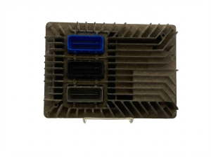
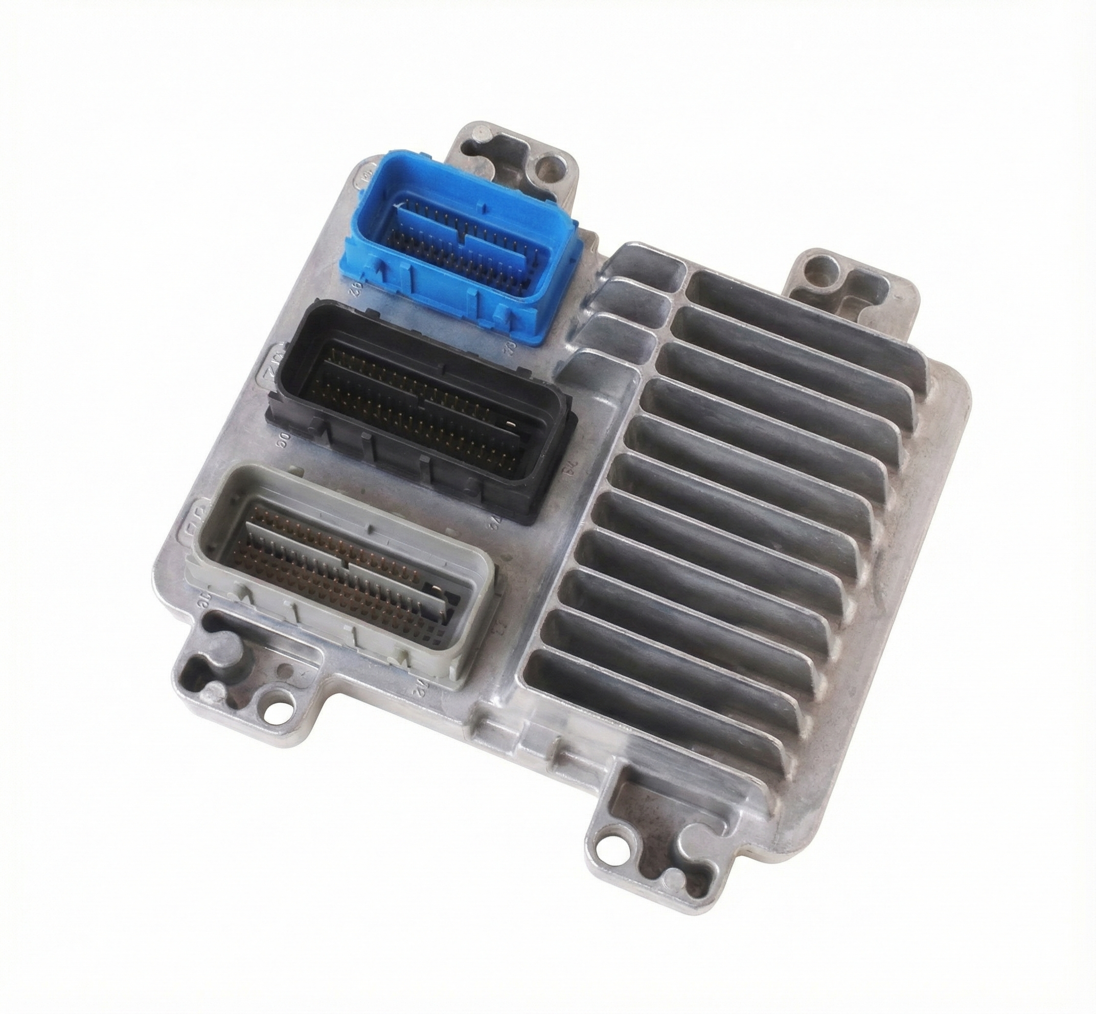
- ECM Connector Pins (2006 Example) — At the ECM itself.. Per TSB #PIC5460B, Pin 19 (PK/BK wire) is Ignition 1 Voltage (Circuit 5290) and Pin 48 (PU wire) is Class 2 Serial Data (Circuit 1807). These are the specific pins to test for correct voltage and data signal when diagnosing a Gen 1 vehicle.
Real Owner Repair Stories
- Reddit user JJJ6hundred (2005 Cadillac CTS 3.6L) — No crank, no start, key gets stuck in ignition, security light on, U0100 is the only code. Occurred after major engine work (camshaft replacement).
❌ Tried (didn't work) Resetting the ECM, key relearn procedure.
✅ What actually fixed it The user discovered that by jumping the starter solenoid directly one time, the communication issue would be temporarily bypassed. Afterwards, the car would start and run normally with the key. However, if the car sat for over an hour, the problem would return. This strongly suggests an intermittent power feed or ground issue to a primary module (likely the ECM) that was disturbed during the engine work, preventing the proper startup 'handshake'. - LS1Tech forum user (2006 Cadillac CTS-V) — Sudden horrible vibration and misfire on one entire bank of cylinders (5,6,7,8) immediately after a car wash while the engine was running.
✅ What actually fixed it The immediate advice given by other members, pointing to a resolution, was to check for water intrusion in the two large harness connectors located to the right of the underhood fuse box, and also to inspect the wiring harness where it routes under the radiator and connects to the PCM. The symptoms occurring directly after a wash strongly indicated water had shorted a power or data line supplying one bank of coils.
Model Year Variations Within This Range
- 2004-2007 (Gen 1): These models use a single-wire Class 2 serial data bus (Circuit 1807). Diagnosis focuses on checking this single purple wire (at ECM pin 48) for a toggling ~7V signal or shorts to power/ground.
- 2008-2011 (Gen 2): These models use a two-wire, high-speed GMLAN (CAN bus). Diagnosis involves checking for ~60 Ohms of resistance between pins 6 and 14 of the DLC (with battery disconnected) and observing the differential voltage signals (~2.5V resting, changing to ~3.5V and ~1.5V when active).
Helpful Videos


We Have This Part in Stock

The information in this article is provided for general reference and educational purposes only. Vehicle specifications, procedures, and part compatibility can vary by production date, trim level, and region. Always consult your vehicle's factory service manual and verify part numbers before purchasing or performing repairs. Safety-critical components such as airbags, seat belts, and braking systems should be installed by a qualified professional.
- Cadillac CTS:
- 🧭 Diagnostic Flowchart
- 🎬 Helpful Videos
- 🛍️ Shop This Part
- What's Unique About the 2004-2011 Cadillac CTS
- Symptoms You May Notice
- Most Likely Causes
- Rare But Worth Checking
- Diagnosis Steps
- Parts You'll Likely Need
- Related Codes That Often Appear With This One
- Technical Service Bulletins (TSBs) & Recalls
- Platform-Specific Known Issues
- Mechanic-Grade Diagnostic Values
- Hidden / Shadow Codes Worth Checking
- Scan Tool Commands That Help
- Wiring & Ground Locations
- Real Owner Repair Stories
- Model Year Variations Within This Range
- 🎟️ Get 5% Off