
U0100 on 2006-2011 Cadillac STS: Lost Communication with ECM Causes and Fixes
On a 2006-2011 Cadillac STS, code U0100 is most often caused by a poor connection at the transmission wiring harness connector (X1), not a failed Engine Control Module (ECM). Inspecting and securing the pins in this connector, as outlined in GM Technical Service Bulletin PIC4740F (superseding PIC4740E), is the most likely and cost-effective fix before suspecting any control modules.
- U0100 on a 2006-2011 Cadillac STS is a critical fault that can cause a no-start or stalling. Do not drive the vehicle.
- Before suspecting a bad ECM, inspect the transmission wiring connector (X1) for loose pins, as this is a known issue documented in TSB PIC4740E.
- Always check the battery voltage and ground connections early in your diagnosis, as low voltage is a common cause of communication codes.
- This is not a simple DIY fix. Professional diagnosis is strongly recommended to avoid replacing expensive parts unnecessarily.
What's Unique About the 2006-2011 Cadillac STS

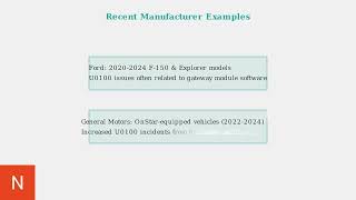
For this specific generation of Cadillac STS and its platform mates (like the CTS and SRX), a U0100 code is frequently a wiring issue rather than a failed computer. General Motors issued a Technical Service Bulletin (PIC4740F) that directly links this code, along with many other communication codes, to unseated or loose pins in the main transmission wiring harness connector (X1). Owners and technicians should investigate this specific, well-documented failure point before considering a costly ECM replacement.
🎬 Watch: Step-by-step diagnosis and solutions for the U0100 code.Diagnostic Flowchart

Tap your situation to follow the diagnostic path that matches what you're seeing on this vehicle.
Symptoms You May Notice

- Check Engine Light is on
- Vehicle will not crank or start
- Engine stalls intermittently
- Transmission shifts harshly or defaults to a single gear
- Multiple warning lights on the dashboard (e.g., ABS, Traction Control, Security)
- Reduced engine power or "limp mode"
- Door locks may cycle while driving
- Key may get stuck in ignition after a failed start attempt
- Replacing the Engine Control Module (ECM) before thoroughly inspecting the transmission connector (X1) and all related power and ground circuits. The TSB for this vehicle platform strongly suggests a wiring fault is the most probable cause.
Most Likely Causes

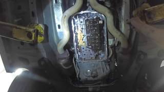
- Loose or Poorly Seated Terminals in Transmission Connector (X1) 🔴 High Probability → Shop Transmission Assembly This is a documented issue addressed by GM in Technical Service Bulletin PIC4740F. The design of the connector or harness routing can lead to pins becoming unseated over time, causing intermittent loss of communication. A side load on the wires can give a false sense of being locked in.
How to confirm: Locate and disconnect the X1 transmission harness connector. It is a large, multi-pin connector on the transmission body. Visually inspect for corrosion or damage, then gently tug on each individual wire to ensure the terminal pins are fully seated and locked in place.
Typical fix: Reseat any loose terminals. If terminals are damaged, corroded, or won't lock, they may need to be replaced. In severe cases, the entire connector pigtail is replaced. Applying dielectric grease during reassembly can help prevent future moisture intrusion.
Est. part cost: $10-$75 - Low Battery Voltage or Poor Ground Connections 🟡 Medium Probability → Shop Vehicle Battery Modern control modules are highly sensitive to voltage. A weak battery, corroded terminals, or a faulty ground strap can cause unpredictable communication errors across the entire CAN network, often triggering a U0100 code.
How to confirm: Test the battery voltage; it should be at least 12.5 volts with the engine off. Inspect and clean the main battery terminals, chassis grounds, and the engine-to-chassis ground strap. Key ground points for the ECM/TCM on GM vehicles are often labeled G101, G102, etc., and their locations can be found in service manuals.
Typical fix: Recharge or replace the battery. Clean or replace corroded terminals and ground straps. Ensure all ground connections are tight and free of paint or rust.
Est. part cost: $0-$250 - Damaged CAN Bus Wiring Harness ⚪ Low Probability Wiring can be damaged by chafing against the chassis or engine components, rodent damage, or previous improper repairs. The TSB also notes to check for harness chafing near the securing bracket for the transmission connector.
How to confirm: Visually inspect the wiring harnesses between the ECM, TCM, and underhood fuse box for any signs of chafing, melting, or rodent damage. A technician can use a multimeter to check for proper resistance (around 60 ohms between CAN High and CAN Low) and voltage (around 2.5V on each line) on the network.
Typical fix: Repair the damaged section of the wiring harness. This is labor-intensive and requires precision.
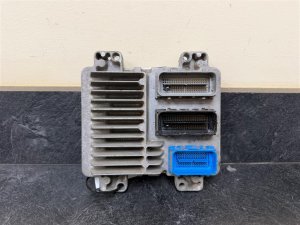
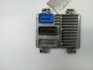
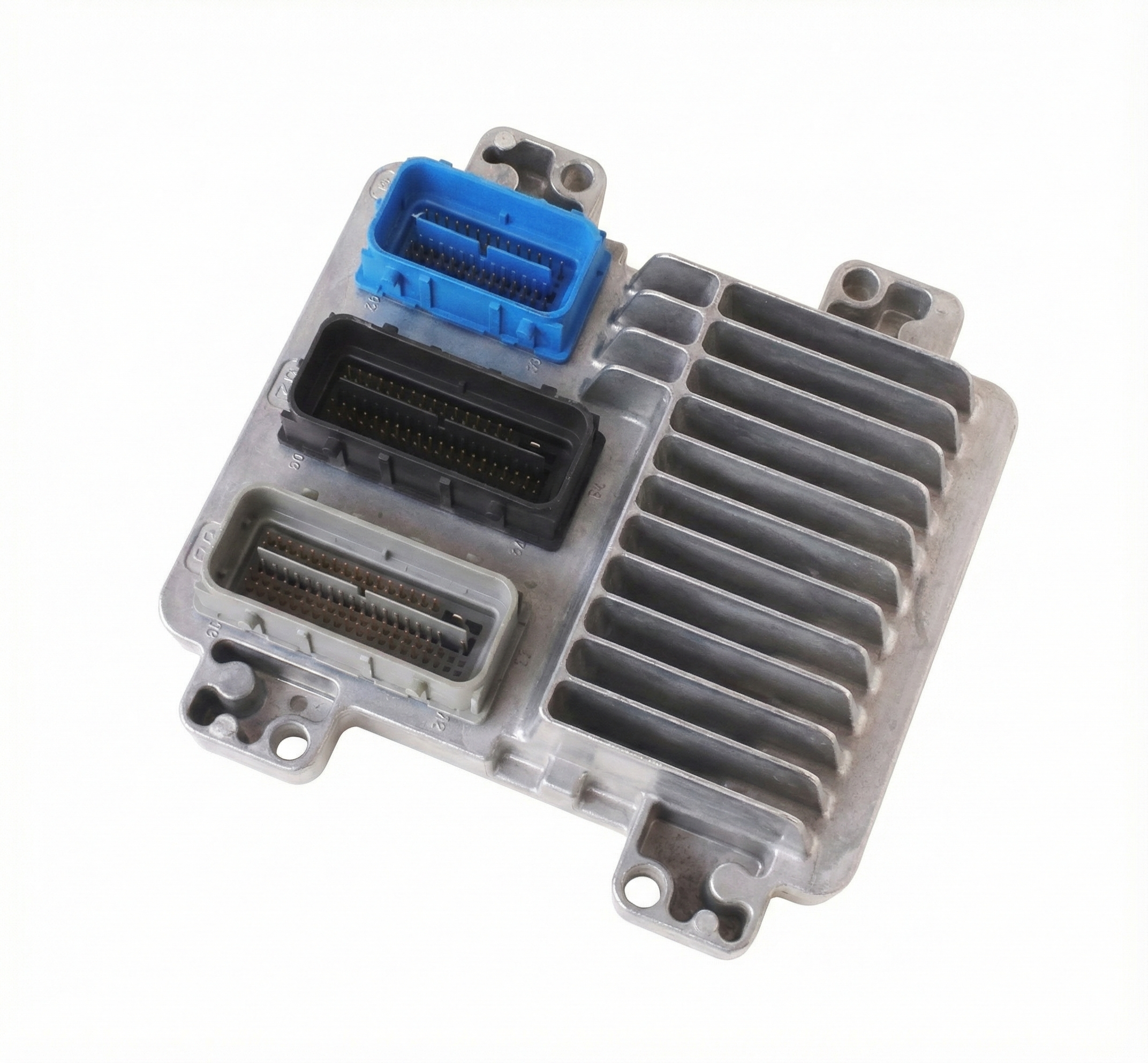
Est. part cost: $10-$100 - Failed Engine Control Module (ECM) ⚪ Low Probability → Shop Engine Control Module (ECM)
How to confirm: This should be the last step after all wiring, connectors, and power/ground sources have been confirmed to be good. A professional scan tool will be unable to communicate with the ECM, even when connected directly, and all power/ground inputs to the ECM test correctly.
Typical fix: Replace the ECM. The new module must be programmed to the vehicle's VIN and security system (key relearn).
Est. part cost: $800-$1200
Rare But Worth Checking
- Faulty Underhood Fuse Box: In some GM vehicles, internal corrosion or a loose connector block within the fuse box itself can cause a loss of power or communication to the ECM. One owner of a similar platform found a loose grey connector under the fuse box was the cause of a no-crank and U0100 code.
- Faulty Ignition Switch: A worn or faulty ignition switch may not provide the proper 'run/crank' signal to all modules, preventing the ECM from 'waking up' and establishing communication on the CAN bus, leading to a U0100 code.
Diagnosis Steps
- Check and record all stored DTCs from all available modules using a professional-grade scan tool. Note which modules are not communicating.
- Check the battery state of charge (should be >12.5V) and inspect all battery terminals and primary ground connections (engine block to chassis, battery to chassis) for tightness and corrosion.
- Inspect all fuses related to the ECM, PCM, and TCM in the underhood fuse box.
- Following GM TSB PIC4740F, locate the X1 connector on the transmission. Disconnect it and inspect the terminals for corrosion, damage, or signs of being unseated.
- Gently pull on each wire going into the X1 connector to confirm the terminal is securely locked in place. A side load can create a false lock, so be thorough.
- If the connector and terminals are in good condition, inspect the wiring harness for any visible damage, especially where it might rub against the engine, transmission housing, or chassis brackets.
- If no visible issues are found, a technician should perform CAN bus network diagnostics. This includes checking for 60-ohm resistance across pins 6 and 14 of the DLC and verifying power and ground at the ECM connector.
- Only after confirming all wiring, connectors, and power/grounds are good should a failed ECM be considered.
Parts You'll Likely Need
- Transmission Connector Pigtail/Terminals
(OEM #Varies. Examples include ACDelco PT2723 or PT1231, but must be visually matched. A full harness is GM part 24046896.)— This is the most likely failure point according to GM's own service bulletin for the U0100 code on this vehicle.
Trusted brands: ACDelco, Dorman
OEM price range: $40-$80
Aftermarket price range: $20-$50 - Engine Control Module (ECM)
(OEM #e.g., 12633238 (part number can vary by year and specific calibration, always verify with VIN))— This is a last resort part that is only replaced after all wiring and connection issues have been ruled out. It is a common misdiagnosis. Requires programming.
Trusted brands: ACDelco (Remanufactured)
OEM price range: $250-$500 (plus core charge)
Aftermarket price range: $200-$400
Related Codes That Often Appear With This One
- U0101 — Lost Communication with TCM. This code is often set alongside U0100 because the faulty transmission connector (X1) directly affects the TCM's ability to communicate.
- U0121 — Lost Communication with ABS Control Module. A general CAN bus network failure will prevent multiple modules from communicating.
- U0140 — Lost Communication with Body Control Module. Another common code indicating a widespread network problem.
- U2100 — Controller Area Network (CAN) Bus Communication. This is a general code indicating a problem on the network, often appearing with more specific 'U' codes.
- P0700 — Transmission Control Module (TCM) Requested MIL Illumination. The TCM sets this code to tell the ECM to turn on the Check Engine Light when it detects a transmission-related fault, such as a loss of communication.
Technical Service Bulletins (TSBs) & Recalls
- PIC4740F: Supersedes PIC4740E. Addresses various communication DTCs including U0100, U0101, and U2100. It instructs technicians to inspect the transmission X1 connector terminals for a loose or poor fit as the primary cause on 2006-2011 STS, as well as SRX, CTS, and ATS models.
Platform-Specific Known Issues
- A known issue documented in TSB PIC4740F (superseding PIC4740E) points to loose pins in the transmission X1 connector causing loss of communication with the ECM, TCM, and other modules. Symptoms include a no-start condition, harsh shifting, and multiple warning lights.
Mechanic-Grade Diagnostic Values
- CAN Bus Resistance (Battery Disconnected) — expected: ~60 Ohms. Failure: 120 Ohms indicates an open circuit or a missing terminating resistor. 0-5 Ohms indicates a short between CAN High and CAN Low wires.
- CAN Bus Voltage (Key On, Engine Off) — expected: CAN High (Pin 6 to Ground): ~2.5-2.7V. CAN Low (Pin 14 to Ground): ~2.3-2.5V.. Failure: Voltages that are stuck high, low, or at 0V indicate a short to power, short to ground, or an open circuit.
- ECM/TCM Power Supply Fuse Voltage Drop — expected: < 0.1V. Failure: A significant voltage reading across a fuse indicates high resistance within the fuse block itself, suggesting internal corrosion or a poor connection.
Scan Tool Commands That Help
- Tech2 / Tech2Win: Module Information / Device Information — To get a list of all modules expected on the network and see their communication status (Present/Not Present). This is a primary step to confirm which specific modules are offline.
- GDS2 (Global Diagnostic System 2): Network Diagnostics / Module Ping — For newer vehicles in the range, GDS2 offers more advanced functions to actively test the network health and 'ping' individual modules to verify their response, which is more robust than a simple status check.
Wiring & Ground Locations
- G101 — On the lower front of the engine block.. This is a primary ground location for the Engine Control Module (ECM) and Transmission Control Module (TCM). A poor connection here can directly cause a U0100 code.
- G103 — At the left rear of the engine compartment on the cowl, above the brake booster.. This ground serves the Body Control Module (BCM), Instrument Panel Cluster (IPC), and the Data Link Connector (DLC) itself. A fault here can disrupt communication across multiple systems.
- G105 — At the left front of the engine compartment, often behind the cooling fan relays.. While primarily for lighting and cooling fans, a corroded G105 can introduce electrical noise into the system, potentially affecting sensitive module communications.
- X1 Connector (Transmission) — The main 16-pin pass-through connector on the side of the transmission case. Its exact position and shape differ between the 5-speed (5L40/5L50) and 6-speed (6L50/6L80) transmissions.. This is the specific connector identified in GM TSB PIC4740F as the most likely cause of U0100 and related communication codes due to loose pins.
Real Owner Repair Stories
- CadillacForums.com user report (2006 Cadillac STS V8) — Intermittent no-start, multiple communication codes including U0100, dash lights flickering.
❌ Tried (didn't work) Checking the TSB-specified transmission connector (X1), which appeared fine., Replacing the battery., Checking all related fuses.
✅ What actually fixed it The main engine-to-chassis ground strap was found to be corroded and making a poor connection under the driver's side of the engine. Cleaning the contact points and tightening the strap resolved all issues. - YouTube - ScannerDanner (Cadillac (model with rear battery, similar architecture to STS)) — No crank, no start, multiple warning lights, low voltage reading at the underhood fuse box.
❌ Tried (didn't work) Initial assumption was a bad positive battery cable or fuse box.
✅ What actually fixed it The main ground cable from the engine block to the frame was completely broken off its terminal. The starter current path was interrupted, preventing a crank and causing modules to lose their ground reference, leading to communication faults. - Independent shop diagnostic story (2008 Cadillac STS) — No crank, U0100, security light on, key gets stuck in ignition.
❌ Tried (didn't work) ECM replacement was considered., Battery and grounds were checked and found to be okay.
✅ What actually fixed it A faulty ignition switch. The switch was not sending the proper power signal on the 'run/crank' circuit to 'wake up' the ECM and other modules. Replacing the ignition switch restored the power-up sequence and communication.
Model Year Variations Within This Range
- 2006-2007 vs 2008-2011: Early models (2006-2007) primarily used the 5-speed 5L40/5L50 automatic transmission. Later models (2008-2011) used 6-speed 6L50 (V6) or 6L80 (V8) transmissions. The critical X1 transmission connector mentioned in the TSB is physically different and in a slightly different location between the 5-speed and 6-speed models, requiring visual confirmation when performing the inspection.
Helpful Videos

Used OEM Parts in Stock
New Aftermarket Parts Available


The information in this article is provided for general reference and educational purposes only. Vehicle specifications, procedures, and part compatibility can vary by production date, trim level, and region. Always consult your vehicle's factory service manual and verify part numbers before purchasing or performing repairs. Safety-critical components such as airbags, seat belts, and braking systems should be installed by a qualified professional.
- Cadillac STS:
- 🧭 Diagnostic Flowchart
- 🎬 Helpful Videos
- 🛍️ Shop This Part
- What's Unique About the 2006-2011 Cadillac STS
- Symptoms You May Notice
- Most Likely Causes
- Rare But Worth Checking
- Diagnosis Steps
- Parts You'll Likely Need
- Related Codes That Often Appear With This One
- Technical Service Bulletins (TSBs) & Recalls
- Platform-Specific Known Issues
- Mechanic-Grade Diagnostic Values
- Scan Tool Commands That Help
- Wiring & Ground Locations
- Real Owner Repair Stories
- Model Year Variations Within This Range
- 🎟️ Get 5% Off