
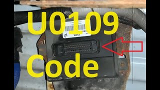
U0109 on 2007-2009 Cadillac SRX: Lost Communication With Fuel Pump Control Module
On a 2007-2009 SRX, U0109 almost always points to a poor connection at the transmission X1 electrical connector, not a bad Fuel Pump Control Module. Inspecting and cleaning this connector is the most likely fix for the common no-start or stalling symptoms. This is a well-documented issue covered in GM Technical Service Bulletin PIC4740F.
- U0109 means the Fuel Pump Control Module (FPCM) is not communicating.
- Do NOT immediately replace the FPCM. The most common cause on this SRX is a bad connection at the transmission X1 connector, per GM TSB PIC4740F.
- This is a critical fault. Do not drive the vehicle, as it can stall without warning or fail to start.
- Symptoms are typically severe, including a crank-no-start or sudden stalling.
- Diagnosis should start with a 'tug test' on the wires at the X1 connector, as specified by the GM service bulletin.
What's Unique About the 2007-2009 Cadillac SRX
For this generation of Cadillac SRX and other similar GM Sigma platform vehicles like the CTS and STS, the U0109 code is famously linked to a known issue that is often not the Fuel Pump Control Module itself. A specific Technical Service Bulletin (TSB PIC4740F, which supersedes PIC4740E) highlights that unseated pins or fretting corrosion at the main transmission harness connector (X1) is a frequent cause of this and many other communication codes. The bulletin instructs technicians to physically tug on each wire at the connector to ensure it is fully seated. This makes checking that specific connector the first and most important diagnostic step, which can save significant time and money on misdiagnosis.
🎬 Watch: Common causes and fixes for the U0109 codeDiagnostic Flowchart
Tap your situation to follow the diagnostic path that matches what you're seeing on this vehicle.
Symptoms You May Notice
- Engine cranks but will not start
- Engine stalls unexpectedly while driving
- Reduced engine power or hesitation
- Check Engine Light is on
- Multiple other warning lights may be on (ABS, Traction Control)
- Other communication codes (U-codes) stored
- Replacing the Fuel Pump Control Module (FPCM) without first inspecting the transmission X1 connector.
- Replacing the in-tank fuel pump when the issue is a communication fault, not a failed pump.
- Replacing the ECM/PCM when the fault lies in the wiring or a different module.
Most Likely Causes
- Poor Connection at Transmission X1 Connector 🔴 High Probability → Shop Transmission Assembly As documented in GM TSB #PIC4740F, the GMLAN communication wires for the FPCM and other modules pass through this single connector, which is highly susceptible to unseated pins or fretting corrosion from vibration and moisture.
How to confirm: Locate the X1 connector on the driver's side of the transmission. Disconnect it and inspect for any bent, loose, or corroded terminals. Per the TSB, perform a 'tug test' by gently pulling on each individual wire at the back of the connector to ensure it is fully seated and locked.
Typical fix: Clean the connector terminals with an appropriate electrical contact cleaner, apply dielectric grease to seal out moisture, and ensure the connector is fully seated. If terminals are loose or damaged, the connector may need to be repinned or replaced with a pigtail kit.
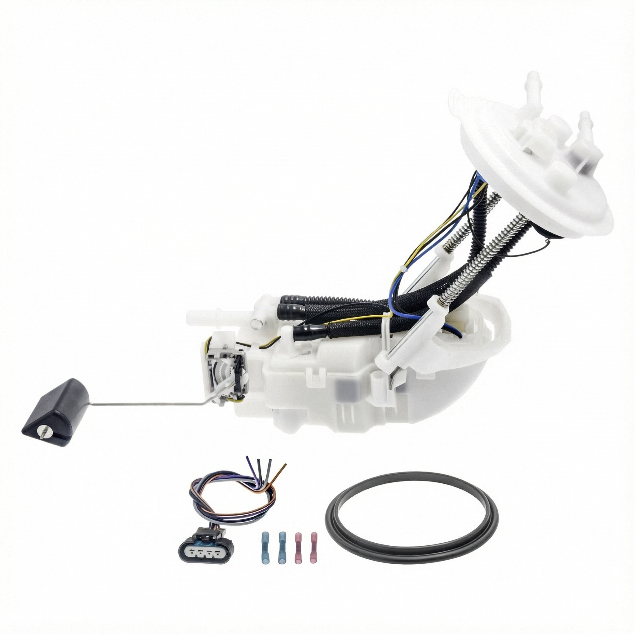
Est. part cost: $10-$50 - Faulty Fuel Pump Control Module (FPCM) 🟡 Medium Probability → Shop Fuel Pump While less common than the connector issue, the module itself can fail due to internal electronic faults, often from heat cycles or moisture intrusion.
How to confirm: After verifying the wiring and connectors are good, diagnosis would require a bi-directional scan tool to attempt to communicate directly with the FPCM. The FPCM is located in the rear cargo area, behind the driver's side trim panel. If communication is not possible despite good power, ground, and data lines at the module connector, the module is likely faulty.
Typical fix: Replace the Fuel Pump Control Module. The new module will require programming to the vehicle's VIN by a dealer or a qualified shop with the correct tools (SPS - Service Programming System).
Est. part cost: $150-$250 - Wiring Harness Damage ⚪ Low Probability The harness can be damaged near exhaust components or where it may chafe against the chassis or other components.
How to confirm: Visually inspect the wiring harness between the ECM, the transmission X1 connector, and the FPCM for any signs of chafing, melting, or rodent damage. Perform continuity and resistance checks on the CAN bus wires (typically Tan and Tan/White wires on GM vehicles).
Typical fix: Repair the damaged section of the wiring harness.
Est. part cost: $5-$100 - Blown Fuse or Poor Ground ⚪ Low Probability
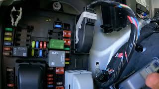
How to confirm: Check the fuse for the FPCM (often labeled 'FSCM' or 'Fuel Pump') in the vehicle's rear fuse box. Locate and inspect the ground connection for the FPCM (likely G402 on the D-pillar) for tightness and corrosion.
Typical fix: Replace the blown fuse (after diagnosing the cause of the overcurrent) or clean and secure the ground connection.
Est. part cost: $1-$10
Diagnosis Steps
- Read all stored DTCs with a quality OBD-II scanner. Note all communication (U-prefix) codes, as a group of them strongly points to a network issue.
- Based on TSB #PIC4740F, the top priority is to inspect the transmission X1 connector. Locate it on the driver's side of the transmission, disconnect it, and check for corrosion or damage.
- Perform a 'tug test' on each wire entering the back of the X1 connector to ensure the pins are fully seated and locked in place.
- If the connector and pins are verified to be good, locate the FPCM in the rear driver's side cargo area behind the trim panel.
- Check the fuse for the FPCM (often labeled 'FSCM' or 'Fuel Pump', typically 20A) in the rear fuse block.
- Using a multimeter, verify that the FPCM connector is receiving proper battery voltage (Red/White wire) and has a solid ground connection (Black wire).
- Test the ECM's turn-on signal at the FPCM connector on the Dark Green/White wire (Pin 13). It should have battery voltage for 2-3 seconds at key-on or constant voltage while cranking.
- Test the CAN bus communication wires for correct resistance (typically 60 ohms between the Tan and Tan/White wires with the battery disconnected). An open or short indicates a wiring problem.
- If all wiring, connectors, power, and grounds are good, the Fuel Pump Control Module is the most likely failed component.
- Confirm the FPCM is faulty using a professional scan tool before ordering a replacement, as it requires VIN-specific programming to function.
Parts You'll Likely Need
- Fuel Pump Control Module
(OEM #Varies, must verify with VIN)— This module can fail electronically, but should only be replaced after verifying wiring and connectors are intact, especially the X1 connector. The part for a 2007-2009 is different from the 2010+ models; VIN verification with a dealer is essential before purchase.
Trusted brands: ACDelco (GM Genuine), Dorman
OEM price range: $180-$250
Aftermarket price range: $120-$180 - Electrical Contact Cleaner — Essential for cleaning corrosion from the transmission X1 connector terminals, which is the most common cause of the fault.
Trusted brands: CRC, DeoxIT
OEM price range: $10-$20
Aftermarket price range: $8-$15 - Dielectric Grease — Applied to the cleaned connector to seal it from future moisture intrusion and prevent corrosion from returning.
Trusted brands: Permatex, CRC
OEM price range: $5-$15
Aftermarket price range: $5-$10
Related Codes That Often Appear With This One
- U0073 — Control Module Communication Bus "A" Off
- U0100 — Lost Communication With ECM/PCM
- U0121 — Lost Communication With Anti-Lock Brake System (ABS) Control Module
- U0140 — Lost Communication With Body Control Module
- P0700 — Transmission Control System (MIL Request)
- P069E — Fuel Pump Control Module Requested MIL Illumination. This often appears when the FPCM detects an internal fault and asks the ECM to turn on the check engine light.
Technical Service Bulletins (TSBs) & Recalls
- PIC4740F: (Supersedes PIC4740E) Titled 'No Crank - Multiple Warning Telltales On - Trans Shifts Hard', this bulletin covers the 2007-2009 SRX. It directs technicians to inspect the transmission X1 connector for unseated pins by performing a 'tug test' on each wire. It lists U0109 as one of the many codes that can be caused by this single connector issue.
- 08-07-30-021H: A broader GM bulletin covering GMLAN communication loss on many trucks and SUVs, including the SRX. It mentions the X1 connector issue and also points to potential chafed wiring, corroded module connectors, and differences in terminating resistors between model years.
Platform-Specific Known Issues
- GM Technical Service Bulletin PIC4740F specifically calls out that a poor connection at the transmission X1 connector can cause U0109 and a wide range of other communication codes. The bulletin advises a 'tug test' on the wires. This is the most critical vehicle-specific issue for this code.
- The Fuel Pump Control Module (FPCM) is located inside the vehicle, in the rear cargo area behind the driver's side trim panel, protecting it from the elements but requiring interior panel removal to access.
- This SRX generation is built on the GM Sigma platform, which is shared with the Cadillac CTS and STS. These vehicles share the same fundamental wiring architecture and are also known to suffer from the U0109 code due to the X1 connector issue.
Mechanic-Grade Diagnostic Values
- High-Speed GMLAN Bus Resistance — expected: 60 Ohms (± 5 Ohms) when measured between Pin 6 and Pin 14 of the DLC with the battery disconnected.. Failure: A reading of ~120 Ohms indicates an open circuit or a fault in one of the two terminating resistors. A reading near 0 Ohms indicates the CAN High and CAN Low wires are shorted together.
- FPCM Power Supply Voltage — expected: Battery Voltage (~12.6V) at the Red/White wire on the FPCM connector with Key On.. Failure: Low or no voltage points to a blown fuse, corroded fuse terminal, or a break in the power wire.
- FPCM Ground Circuit Integrity — expected: Less than 1.0 Ohm of resistance between the Black wire on the FPCM connector and a known good chassis ground.. Failure: High resistance or an open circuit (OL) indicates a corroded, loose, or broken ground connection at a location like G402.
- FPCM Turn-On Signal Voltage — expected: Battery voltage for 2-3 seconds when the key is first turned ON, or constant battery voltage while cranking.. Failure: No voltage on the Dark Green/White wire at Pin 13 indicates the ECM is not commanding the FPCM to turn on, which could be an ECM fault or a break in that specific wire.
- GMLAN Bus Voltage (Live) — expected: Average of ~2.66V on GMLAN High (Tan wire) and ~2.34V on GMLAN Low (Tan/White wire) with key on.. Failure: Voltages stuck high, low, or at 0V indicate a short to power, short to ground, or an open circuit on the bus.
Scan Tool Commands That Help
- Tech 2 / GDS2: Module Communication Status / Network Test — Use this to see which modules are online. If only the FPCM is offline, the fault is isolated to its circuit. If multiple modules are offline, it indicates a network-wide problem, likely at a central point like the X1 connector or a terminating resistor.
- Tech 2 / GDS2: FPCM Data Display — After establishing communication, check the FPCM data list to see if it is reading 'Ignition 1 Voltage' correctly. If it reads 0V despite power being present at the pin, the module itself may be faulty internally.
- GM SPS (Service Programming System): Module Programming/Setup — This is required after replacing the Fuel Pump Control Module. The new module must be programmed with the vehicle's VIN and specific software to function.
Wiring & Ground Locations
- FPCM — Behind the driver's side rear cargo area trim panel.. This is the module that has lost communication. Access is required to test its power, ground, and data lines directly at its connector.
- X1 Connector — The main 16-pin electrical harness connector located on the driver's side of the transmission housing.. This is the location specified in TSB PIC4740F as a primary cause of network failures due to poor pin connections. The GMLAN wires for the FPCM pass through here.
- G402 — A chassis ground point located at the rear of the left rear shock tower, on the 'D' pillar.. This is a likely ground point for the FPCM. Per GM's naming convention, 'G4xx' grounds are in the rear of the vehicle. A loose or corroded connection here will cause the FPCM to lose power and communication.
- FPCM Connector Pins — At the FPCM connector itself.. Key pins for testing are: Power (Red/White wire), Ground (Black wire), and the ECM Turn-On Signal (Dark Green/White wire at Pin 13). The GMLAN data wires are a twisted pair of Tan and Tan/White wires.
- FPCM Fuse — Typically located in the rear fuse block, often labeled 'FSCM' or 'Fuel Pump' and rated at 20A.. This fuse supplies the main operating power to the Fuel Pump Control Module.
Real Owner Repair Stories
- 2CarPros Forum User / Go-Parts Research (GM Truck with similar FPCM wiring architecture) — Crank no start, no communication with FPCM, code U0109.
❌ Tried (didn't work) Checking fuses, Checking ground wires at the module
✅ What actually fixed it Found the FPCM power wire was only receiving 1.4 volts. The wire was found to be broken inside the main wiring loom where it passed through the square tube of the vehicle frame, located under the driver's side fuse panel. An overlay/jumper wire was run to bypass the break, restoring full power and fixing the issue. - YouTube user 'Fix it Angel' (GMC Yukon with U0109) — Crank no start after sitting overnight.
✅ What actually fixed it The FPCM fuse (Fuse #21, 20A) in the underhood fuse box had severely corroded legs, causing a poor connection. Replacing the fuse temporarily restored function, but the ultimate repair required replacing the entire underhood fuse box due to internal corrosion.
Model Year Variations Within This Range
- 2007 vs 2008-2009: According to GM bulletin 08-07-30-021H, the GMLAN network architecture has a subtle difference. On 2007 models, a potential failure point is the 'Terminator Resistor.' On 2008 and newer models, this component is referred to as the 'Data Link Resistor.' While functionally similar, their specific location or integration may differ, affecting network diagnostics.
Helpful Videos


Used OEM Parts in Stock
New Aftermarket Parts Available


The information in this article is provided for general reference and educational purposes only. Vehicle specifications, procedures, and part compatibility can vary by production date, trim level, and region. Always consult your vehicle's factory service manual and verify part numbers before purchasing or performing repairs. Safety-critical components such as airbags, seat belts, and braking systems should be installed by a qualified professional.
- Cadillac SRX:
- 🧭 Diagnostic Flowchart
- 🎬 Helpful Videos
- 🛍️ Shop This Part
- What's Unique About the 2007-2009 Cadillac SRX
- Symptoms You May Notice
- Most Likely Causes
- Diagnosis Steps
- Parts You'll Likely Need
- Related Codes That Often Appear With This One
- Technical Service Bulletins (TSBs) & Recalls
- Platform-Specific Known Issues
- Mechanic-Grade Diagnostic Values
- Scan Tool Commands That Help
- Wiring & Ground Locations
- Real Owner Repair Stories
- Model Year Variations Within This Range
- 🎟️ Get 5% Off