
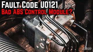
U0121 on 2015-2017 GMC Yukon XL: Lost Communication with ABS Module Causes and Fixes
On 2015-2017 Yukon XLs, U0121 is most often caused by a poor BCM ground at G218 under the driver's dash or a damaged wiring harness under the door sill plates. Inspecting and fixing these common electrical faults, specifically the 'Communication Enable circuit 5986' or splice J365, usually resolves the code without replacing the expensive ABS module.
- Before suspecting an expensive module failure, always inspect the BCM ground G218 under the driver's dash. This is the most likely cause.
- The second most likely cause is corroded or damaged wiring under the plastic door sill plates.
- This fault disables your ABS and Stabilitrak systems, which significantly impacts vehicle safety in emergency maneuvers. Do not delay diagnosis and repair.
- If the code only appears as a 'history' code in the Front View Camera Module (FVCM) with no other symptoms, it is likely a phantom code and can be ignored per a GM TSB.
- Replacing the EBCM requires professional programming to match your vehicle's VIN.
What's Unique About the 2015-2017 Gmc YUKON XL
This generation of GMC Yukon and its K2XX platform siblings (Tahoe, Suburban, Silverado, Sierra, Escalade) is well-documented for specific electrical issues that directly cause the U0121 code. GM has issued multiple Technical Service Bulletins (TSBs) that point to a poorly secured ground point (G218) and compromised wiring under the door sill plates as the root cause for a wide range of communication failures, including U0121. Unlike many other vehicles where the module itself is the primary suspect, on the Yukon XL, these known wiring and grounding issues are the most probable cause and should be investigated first.
Diagnostic Flowchart
Tap your situation to follow the diagnostic path that matches what you're seeing on this vehicle.
Symptoms You May Notice
- ABS warning light is on
- Stabilitrak / Traction Control warning light is on
- "Service Stabilitrak" message on the driver information center
- "Service Brake System" message on the driver information center
- Loss of anti-lock brake function (wheels may lock and skid during hard braking)
- Instrument panel cluster may go blank intermittently (if related to G218 ground issue)
- Radio or HVAC controls may go blank (if related to G218 ground issue)
- Steering may feel heavy or kick back when turning at low speeds (if G218 ground is the cause)
- Replacing the EBCM (ABS Module) without first thoroughly inspecting the G218 ground and the sill plate wiring harnesses. These wiring/ground issues are far more common on this platform and much cheaper to fix.
Most Likely Causes
- Poor Body Control Module (BCM) Ground at G218 🔴 High Probability → Shop Body Control Module As documented in GM TSB #PIT5405C (and its successor #18-NA-161), the dash insulator mat was often trapped under the ground eyelet during manufacturing. This creates high resistance and causes a host of communication codes, including U0121.
How to confirm: Locate G218 under the driver's side dash, near the A-pillar and kick panel speaker. Check if the 10mm nut is loose or if the black dash insulation is caught under the ground terminal. A voltage drop test from the ground wire to a clean chassis point will confirm high resistance.
Typical fix: Disconnect the battery. Remove the 10mm nut, pull the wire eyelet off the stud, and use a knife to trim away any interfering insulation from around the stud. Clean the contact surfaces of the eyelet and body with a wire brush, then securely retighten the nut to 7 Nm (62 lb-in).
Est. part cost: $0 - Damaged Wiring Harness Under Door Sill Plates 🔴 High Probability As documented in GM TSB #PIT5457D, the wiring harness that runs under the driver and passenger sill plates is susceptible to moisture, which leads to corrosion and damage. The 'Communication Enable circuit 5986' and a splice point known as 'J365' (under the passenger sill plate) are common failure points.
How to confirm: Remove the driver and passenger side plastic door sill plates to access the wiring channel. Carefully unwrap the harness tape and inspect the wires, especially the Communication Enable wire (circuit 5986), for signs of corrosion (green or white powder), pinched wires, or previous water intrusion.
Typical fix: Repair any broken or corroded wires. This involves cutting out the damaged section, splicing in a new piece of wire using solder and sealed heat-shrink connectors, and re-wrapping the harness to protect it from future moisture.
Est. part cost: $5-$25 - Faulty Electronic Brake Control Module (EBCM) 🟡 Medium Probability → Shop ABS Control Module While less common than wiring issues on this platform, the module can fail internally due to vibration, heat, or age. Its location on the driver's side frame rail also makes its 38-pin connector susceptible to corrosion.
How to confirm: After confirming all power, ground, and communication wires (CAN bus and Circuit 5986) have good continuity and voltage at the EBCM connector, the module itself is the likely culprit. This requires a multimeter and wiring diagram.
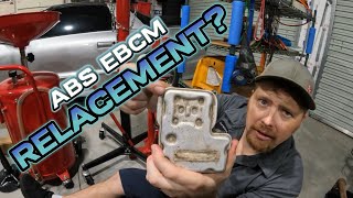
Typical fix: Replace the EBCM. The new module must be programmed to the vehicle's VIN by a dealer or a qualified shop with the proper software (e.g., ACDelco's Techline Connect).
Est. part cost: $400-$1350 - Low Battery Voltage or Poor Battery Connections ⚪ Low Probability → Shop Vehicle Battery Modern control modules are sensitive to voltage. A weak battery or corroded terminals can cause a variety of unpredictable communication errors across the CAN bus network.
How to confirm: Test the battery with a multimeter. It should have at least 12.4V with the engine off and 13.7-14.7V while running. Inspect battery terminals for corrosion and ensure the cable clamps are tight and cannot be rotated by hand.
Typical fix: Clean battery terminals or replace the battery if it fails a load test. Tighten cable clamps to the specified 7 Nm (62 lb-in).
Est. part cost: $0-$250
Rare But Worth Checking
- History Code from Front View Camera Module (FVCM): According to TSB #PIT5599, a software anomaly can cause a false U0121 code to be stored in the history of the FVCM with each ignition cycle. If the code is only present as a history code in the FVCM and there are no other symptoms or warning lights, GM advises that it should be ignored and no repairs should be performed.
- EBCM Harness Abrasion Near Transmission: → Shop Transmission Assembly A GM document notes that the EBCM body wiring harness can be mis-clipped from the factory, allowing it to rub against a transmission mounting bolt. This can cause abrasion, shorted wires, blown fuses, and a no-start condition along with communication codes like U0121. Inspection requires locating the harness branch behind the radiator surge tank.
Diagnosis Steps
- Scan for Codes: Use a high-quality OBD-II scanner capable of reading codes from all modules (ABS, BCM, ECM, etc.). Note all active and history codes and in which modules they are stored.
- Check Battery Health: Verify battery voltage is above 12.4V engine-off and the charging system is working correctly (13.7-14.7V engine-on). Clean battery terminals and ensure clamps are tight.
- Inspect Ground G218: This is the most critical first step. Locate ground G218 under the driver's side dash near the A-pillar. Disconnect the battery, remove the 10mm nut, and check for trapped dash insulation. Trim away any insulation, clean the contacts to bare metal, and tighten the nut securely. 🎬 Watch: Step-by-step guide to fixing the G218 ground issue.
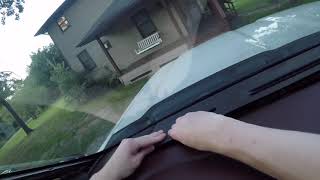
- Inspect Sill Plate Wiring: Remove the plastic sill plates on both the driver and passenger sides. Carefully unwrap and inspect the wiring harnesses for any signs of corrosion (green/white powder), water damage, or pinched wires, paying close attention to the Communication Enable circuit 5986 and splice J365 under the passenger side. 🎬 See how to diagnose and fix these common wiring failures.
- Check ABS Fuses: Check all fuses related to the ABS/EBCM system in both the under-hood and interior fuse panels.
- Test EBCM Connector: If the above steps do not resolve the issue, disconnect the EBCM's 38-pin connector. Using a multimeter and a wiring diagram, test for proper power, ground, and the ~12V wake-up signal on circuit 5986 (key on). Test CAN bus network resistance between the CAN High and CAN Low wires; it should be ~60 ohms.
- Condemn EBCM: Only if all wiring, grounds, and power sources test good should the EBCM be considered faulty.
Parts You'll Likely Need
- Electronic Brake Control Module (EBCM)
(OEM #23380704 (representative for 2015-2016, always verify with VIN))— This part is only needed if all wiring and ground issues have been ruled out. It is the control computer for the ABS and Stabilitrak systems and requires programming. 🎬 Watch: A complete walkthrough for replacing the EBCM module.
Trusted brands: ACDelco (GM Genuine)
OEM price range: $700-$1350
Aftermarket price range: $400-$800 - Wiring Repair Supplies — Often the actual fix is repairing corroded wires under the sill plates. This requires wire, butt connectors, heat shrink tubing, and Tesa tape.
Trusted brands: 3M, Tesa
OEM price range: $10-$30
Aftermarket price range: $10-$30
Related Codes That Often Appear With This One
- U0073 — Control Module Communication Bus 'A' Off. This is a general network code that often appears with U0121, indicating a broader communication problem, frequently stemming from the G218 ground fault.
- U0100 — Lost Communication with ECM/PCM. Often appears when the G218 ground is faulty, as it affects multiple modules.
- U0126 — Lost Communication With Steering Angle Sensor Module. This module is on the same communication bus and is often affected by the same wiring issues. TSB #PIT5405C lists it as a related code.
- U0140 — Lost Communication With Body Control Module. This is a key code that points directly to a BCM-related issue, such as its main ground (G218). TSB #PIT5405C lists it as a related code.
- U0131 — Lost Communication With Power Steering Control Module. Also listed in TSBs related to G218 and sill plate wiring issues.
Technical Service Bulletins (TSBs) & Recalls
- PIT5405C: Addresses various electrical issues including U0121 caused by a poor BCM ground at G218 due to trapped dash insulation.
- 18-NA-161: Successor to PIT5405C, reiterating the G218 ground inspection and repair procedure for models up to 2020.
- PIT5457/A/B/D: A series of bulletins addressing loss of communication with various modules (EBCM, PSCM, etc.) due to damaged or corroded wiring (specifically circuit 5986) under the door sill plates.
- PIT5599: Advises ignoring a history-only U0121 code stored in the Front View Camera Module (FVCM) as it is a known software anomaly.
Platform-Specific Known Issues
- A poor ground at G218 is a well-documented cause for a multitude of electrical issues and communication codes, including U0121, as detailed in TSB #PIT5405C.
Mechanic-Grade Diagnostic Values
- Communication Enable Circuit 5986 Voltage — expected: Approximately 12V with key in ACC, ON, or START. Should be able to light a small test light or a 194 bulb.. Failure: Low or no voltage indicates an open or high resistance in the circuit, often under the sill plates.
- High-Speed GMLAN Bus Voltage (at DLC) — expected: CAN High (Pin 6) averages ~2.6V, CAN Low (Pin 14) averages ~2.4V with ignition on. During communication, High toggles toward 3.5V and Low toggles toward 1.5V.. Failure: Voltages that are stuck, do not mirror each other, or are shorted to ground/power.
- CAN Bus Termination Resistance — expected: Approximately 60 Ω when measured between CAN High (Pin 6) and CAN Low (Pin 14) at the DLC with the battery disconnected.. Failure: A reading of ~120 Ω indicates one of the two terminating resistors (or the wiring to it) has failed. Infinite or very low resistance indicates a bus wiring fault (open or short).
- Load Test of Communication Enable Circuit 5986 — expected: When a 194 bulb is connected between circuit 5986 at the module and a good ground, the bulb should light and the voltage across the bulb should be at least 11V.. Failure: If the bulb does not light or voltage drops below 11V, it confirms high resistance in the circuit that may not be apparent with a high-impedance multimeter alone.
Scan Tool Commands That Help
- GDS2 (GM Techline Connect): SPS (Service Programming System) — This function is required after replacing the Electronic Brake Control Module (EBCM). It downloads the correct calibration and software from GM's servers and flashes it to the new module, programming it to the vehicle's VIN.
- GDS2 (GM Techline Connect): Module Status / Network Test — Before diving into wiring, use the scan tool to request status from all modules on the network. This quickly confirms which modules are offline. If only the EBCM is missing, the fault is isolated to that module's circuit. If multiple modules are offline, it points to a larger network or BCM issue.
- Professional Bi-Directional Scanner: Automated Bleed — After replacing the EBCM or performing hydraulic repairs to the brake system, this function must be used. It cycles the internal ABS pump and valves to purge any trapped air from the hydraulic block, which cannot be done with a manual bleed.
Wiring & Ground Locations
- G218 — Under the driver's side dash, on the A-pillar frame behind the kick panel, near the hood release and speaker.. This is the primary ground for the Body Control Module (BCM). High resistance here due to trapped insulation or looseness causes widespread communication faults, including U0121.
- Splice J365 — Under the passenger's front door sill plate, within the main wiring harness.. This is a known weak point for the 'Communication Enable circuit 5986'. Corrosion or damage at this splice can cut the wake-up signal to the EBCM and other modules.
- EBCM Connector (X1) — On the Electronic Brake Control Module, which is mounted to the driver's side frame rail, under the vehicle.. This 38-pin connector is the main interface for the EBCM. It must be checked for corrosion and tested for power, ground, and communication signals (CAN bus and Circuit 5986) to rule out a wiring issue before condemning the module.
- Driver's Sill Plate Harness — In the wiring channel running under the plastic door sill trim on the driver's side.. This harness is a common location for damage to the Communication Enable circuit 5986 due to water intrusion or chafing, as noted in TSB #PIT5457D.
Real Owner Repair Stories
- YouTube video by Robert Dotterer (Dotterer's Auto Service) (2015 Mazda 3 (demonstrating a universal diagnostic principle)) — Check engine light, vehicle in limp mode, multiple 'lost communication with ABS' codes from various modules.
❌ Tried (didn't work) Replaced ABS module, Replaced Body Control Module (BCM), Replaced Air Bag Module
✅ What actually fixed it A bad ground connection for the ABS module was found. The ground bolt was loose. After cleaning and tightening the ground connection, communication was restored and the codes were resolved. This was confirmed by performing a load test on the ground wire with a headlight bulb, which revealed the high resistance.
OEM Part Supersession History
23154722→23380704— Standard part revision by the manufacturer.
Heads up: Part 23380704 is specified for 2015-2016 models with JD9 brakes. It requires programming via SPS after installation.23355954, 84074957, 84074960, 84256789→84256781— Multiple revisions consolidated into a new part number.
Heads up: Part 84256781 is specified for 2017-2020 models with JD9 brakes. Always verify the correct part number with the vehicle's VIN, as multiple brake options exist.
Model Year Variations Within This Range
- 2017-2020: The part number for the EBCM appears to change for the 2017 model year. While 2015-2016 models commonly use PN 23380704, 2017 and newer models often use PN 84256781 or its supersessions. Using the wrong part will likely result in programming failure.
Helpful Videos


We Have This Part in Stock

The information in this article is provided for general reference and educational purposes only. Vehicle specifications, procedures, and part compatibility can vary by production date, trim level, and region. Always consult your vehicle's factory service manual and verify part numbers before purchasing or performing repairs. Safety-critical components such as airbags, seat belts, and braking systems should be installed by a qualified professional.
- Gmc YUKON XL:
- 🧭 Diagnostic Flowchart
- 🎬 Helpful Videos
- 🛍️ Shop This Part
- What's Unique About the 2015-2017 Gmc YUKON XL
- Symptoms You May Notice
- Most Likely Causes
- Rare But Worth Checking
- Diagnosis Steps
- Parts You'll Likely Need
- Related Codes That Often Appear With This One
- Technical Service Bulletins (TSBs) & Recalls
- Platform-Specific Known Issues
- Mechanic-Grade Diagnostic Values
- Scan Tool Commands That Help
- Wiring & Ground Locations
- Real Owner Repair Stories
- OEM Part Supersession History
- Model Year Variations Within This Range
- 🎟️ Get 5% Off