
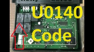
U0140 on 2013-2015 Cadillac ATS: Lost Communication With Body Control Module Fixes
On a 2013-2015 Cadillac ATS, code U0140 almost always points to a wiring issue, not a failed Body Control Module (BCM). A GM Technical Service Bulletin (TSB PIC4740E) identifies a poor connection at the transmission's main X1 electrical connector, located on the driver's side of the transmission, as the primary cause. Inspecting, cleaning, and securing this specific connector should be the first step before any parts are replaced.
- U0140 on a 2013-2015 ATS is most likely a wiring problem, not a bad BCM.
- Always inspect the transmission X1 electrical connector first, as per GM TSB #PIC4740E.
- Do not replace the expensive Body Control Module until all wiring and connector checks have been completed.
- Due to the complexity of network diagnostics, professional service is highly recommended if the initial connector inspection doesn't solve the problem.
What's Unique About the 2013-2015 Cadillac ATS
While U0140 points to the Body Control Module, the most common cause on this specific GM Alpha platform is often unrelated to the BCM itself. A well-documented issue, highlighted in GM TSB #PIC4740E, points to loose, unseated, or corroded terminals in the transmission's main X1 electrical connector. This large, round, lever-actuated connector is on the driver's side of the transmission, and faults here can disrupt the entire communication network, making the BCM appear offline even when the module is perfectly fine. The TSB specifically instructs technicians to tug on each wire in the connector to ensure the pins are fully seated.
Diagnostic Flowchart
Tap your situation to follow the diagnostic path that matches what you're seeing on this vehicle.
Symptoms You May Notice
- Multiple warning lights on the dashboard, especially for StabiliTrak, ABS, and Traction Control.
- "Service StabiliTrak" message on the driver information center (DIC).
- Malfunctioning or inoperative power windows, door locks, and interior lights.
- Exterior lights (headlights, turn signals) behaving erratically or not working.
- Key fob or keyless entry system not working.
- Harsh shifting or transmission defaulting to a single gear.
- Instrument cluster gauges behaving erratically or going blank.
- Vehicle may not start (no-crank) or may stall intermittently.
- Replacing the Body Control Module (BCM) before thoroughly inspecting all related wiring and connectors, especially the transmission X1 connector mentioned in TSB PIC4740E.
- Replacing wheel speed sensors or ABS modules for StabiliTrak warnings without first checking for network communication codes like U0140. 🎬 Watch: Understanding the causes and fixes for the U0140 code
Most Likely Causes
- Loose or Corroded Terminals in Transmission X1 Connector 🔴 High Probability → Shop Transmission Assembly This is a known issue documented by General Motors in Technical Service Bulletin #PIC4740E. The connector is located on the driver's side of the transmission, where it is exposed to vibration, heat, and moisture, leading to unseated or corroded terminal pins over time.
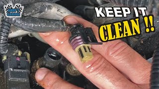
How to confirm: Visually inspect the large, round X1 electrical connector on the driver's side of the transmission. Disconnect it and check for any loose, bent, or corroded pins. Per the TSB, you should gently tug on each individual wire going into the connector to ensure the terminal is fully seated and locked in place. Wiggling the harness while the vehicle is running (if possible) may cause symptoms to appear or disappear.
Typical fix: Disconnect the connector and clean the pins and sockets with electrical contact cleaner. Apply a thin layer of dielectric grease to the seal before reconnecting 🎬 Watch: Pro tips for cleaning and protecting electrical connectors to prevent moisture intrusion. If pins are damaged or will not stay seated, the connector may need to be repinned or a pigtail harness spliced in.
Est. part cost: $5-$50 - Damaged or Chafed CAN Bus Wiring Harness 🟡 Medium Probability Wiring harnesses can rub against chassis or engine components over time, causing wires to fray or short out. TSB #PIC4740E specifically calls out inspecting the harness securing bracket on the passenger side of the transmission bell housing on the ATS for potential chafing.
How to confirm: Visually inspect all visible sections of the main wiring harness, particularly where it bends or is secured near the engine, transmission, and firewall. Pay close attention to the bracket on the passenger side of the bell housing. Look for signs of abrasion, melting, or damage.
Typical fix: Repair the damaged section of wire. This involves cutting out the bad section, splicing in a new piece of wire using weatherproof connectors, and protecting it with heat shrink tubing or loom.
Est. part cost: $5-$25 - Poor Power or Ground Connection to the BCM ⚪ Low Probability Grounding points can corrode over time, and main ground straps can become loose, creating high resistance. A loose main engine ground cable was found to cause a no-start and get extremely hot on a 2014 ATS. GM also issued a bulletin (07-08-47-004D) warning technicians that disconnecting a BCM ground while the battery is connected can permanently damage the module.
How to confirm: Using a multimeter, verify that the BCM is receiving stable battery voltage (12.2V+) and has a solid ground connection (<0.5 ohms to chassis ground) at its electrical connector. The BCM is located behind the glove box. Key ground points to inspect for tightness and corrosion include G201 (left kick panel) and G302 (right kick panel). Check the main engine-to-chassis ground strap for looseness.
Typical fix: Clean and tighten the faulty power or ground wire connection. This may involve sanding the contact point to bare metal before tightening and applying a protective coating. Replace any corroded ground straps.
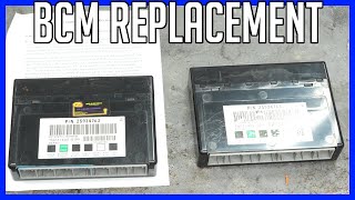
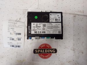
Est. part cost: $10-$40 - Failed Body Control Module (BCM) ⚪ Low Probability → Shop Body Control Module
How to confirm: This should only be considered after all wiring, connectors, and power/ground sources have been thoroughly tested and confirmed to be good. A professional scan tool will be unable to establish communication with the BCM. The BCM itself may have signs of internal failure due to water intrusion or corrosion.
Typical fix: Replace the Body Control Module. The new BCM will require programming by a dealership or a qualified shop with GM-specific software (SPS) to match the vehicle's VIN and options. Some companies offer a mail-in cloning service where they transfer data from your old BCM to a replacement unit.
Est. part cost: $250-$500
Diagnosis Steps
- Check battery health and system voltage. A weak or failing battery can cause numerous communication codes. Voltage should be stable (12.2–13.0V key off, 13.5–14.7V engine running).
- Scan all vehicle modules for stored trouble codes. Note all codes present, especially other U-codes, and which modules are not communicating.
- CRITICAL STEP: Locate the transmission X1 electrical connector on the driver's side of the transmission. Disconnect it and carefully inspect for corrosion, moisture, or damaged pins. Following TSB #PIC4740E, gently pull on each wire to ensure the terminals are fully seated in the connector.
- Inspect the wiring harness for physical damage, chafing, or corrosion. Pay special attention to the harness securing bracket on the passenger side of the transmission bell housing.
- If wiring appears good, check for power and ground at the BCM. The BCM is located behind the glove box. Using a multimeter, check for stable 12V+ power and clean, tight ground connections (check resistance to chassis ground, should be <0.5 ohms). Key grounds are G201 and G302 in the driver/passenger kick panels.
- A professional technician would use an advanced scan tool to check the CAN bus network integrity. This involves measuring resistance between Pin 6 (CAN High) and Pin 14 (CAN Low) at the OBD-II port (should be ~60 ohms with key off) and checking for proper voltage signals with an oscilloscope.
- Only after all wiring, connectors, power, and grounds are confirmed to be good should the BCM be considered faulty.
Parts You'll Likely Need
- Connector Terminals / Pigtail — The most common fix is repairing the transmission X1 connector, which may require new terminal pins if they are corroded, damaged, or unseated.
Trusted brands: ACDelco
OEM price range: $20-$50
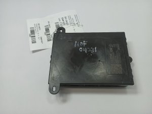
Aftermarket price range: $10-$30 - Body Control Module (BCM)
(OEM #13586589, 13592590)— This is the part to replace only after all wiring and connection issues have been ruled out. It is the least likely cause of the code. Requires programming.
Trusted brands: ACDelco
OEM price range: $300-$500
Aftermarket price range: $200-$400
Related Codes That Often Appear With This One
- U0073 — This is a general network failure code ('Control Module Communication Bus 'A' Off') that often accompanies specific module communication loss codes like U0140. It is explicitly listed in TSB PIC4740E.
- U0100 — Lost Communication With ECM/PCM. This can be set alongside U0140 if the network fault at the transmission connector is severe enough to disrupt communication with multiple critical modules.
- U0121 — Lost Communication With Anti-Lock Brake System (ABS) Control Module. The ABS module relies on data from the BCM and other modules, so a network fault will often trigger this code. It is also listed in TSB PIC4740E.
- P0700, C0561, etc. — TSB PIC4740E explicitly lists a wide range of transmission (P0700), chassis (C0561), and other codes that can be stored along with U0140, all stemming from the same root cause of a poor connection at the transmission harness.
Technical Service Bulletins (TSBs) & Recalls
- PIC4740E: States that with U0140 and many other codes, technicians should inspect the transmission X1 connector terminals for loose or poor fit and check for harness chafing near the bell housing. This is the primary diagnostic path.
- 07-08-47-004D: Warns technicians to disconnect the negative battery cable before removing any BCM ground connections to prevent damaging the module.
Platform-Specific Known Issues
- GM Technical Service Bulletin #PIC4740E directly addresses this code, along with many others, on the 2013-2015 Cadillac ATS. It points technicians to inspect the transmission X1 connector for loose or poorly fitting terminals as the primary cause of the communication loss.
- The same TSB also advises checking for a chafed harness at the securing bracket on the passenger side of the transmission bell housing specifically on the ATS and CTS models.
- A separate GM bulletin (07-08-47-004D) warns that the BCM can be internally damaged if a ground path is removed while the module is powered, emphasizing the need to disconnect the negative battery cable before servicing BCM-related grounds.
Mechanic-Grade Diagnostic Values
- CAN Bus Network Resistance — expected: ~60 Ω (Ohms) with a tolerance of ±5 Ω.. Failure: A reading of ~120 Ω indicates one of the two terminating resistors is missing from the circuit (likely an unplugged module). A reading near 0 Ω indicates a short between the CAN High and CAN Low wires.
- CAN Bus Voltage — expected: CAN High (Pin 6 to Ground): ~2.6V. CAN Low (Pin 14 to Ground): ~2.4V. The total voltage between High and Low should be close to 5V.. Failure: Significant deviation from these voltages, or voltages that don't change with network activity, can indicate a short, open, or a faulty module transceiver.
- BCM Ground Circuit Resistance — expected: < 0.5 Ω to a clean chassis ground point.. Failure: Higher resistance indicates a corroded or loose ground connection, which can starve the module of a stable reference voltage.
Hidden / Shadow Codes Worth Checking
- U0140 SYMXX: GM uses 'symptom bytes' (a two-digit code like SYM00) to provide more specific information about a generic 'U' code. These can differentiate between 'No Communication', 'Invalid Data', or other failure modes not visible with a standard OBD-II reader. (see via Requires a dealer-level scan tool like the GM GDS2 (Global Diagnostic System 2) or a high-end professional scanner with GM-specific software.)
Scan Tool Commands That Help
- GM GDS2: Module Diagnostics -> Body Control Module -> Control Functions — This is used to verify if the BCM itself is functional. If the scan tool can't communicate with the BCM at all, it points to a network or power/ground issue. If it can communicate, you can use bidirectional controls to command outputs like headlights, door locks, or wipers. If the commands work, the BCM and its output circuits are likely good, and the problem is on the input or communication side. If they don't work, it points towards a potential BCM failure.
Wiring & Ground Locations
- G201 — In the upper left corner of the instrument panel, near the A-pillar, behind the left kick panel.. This is a primary ground point for several instrument panel and driver-side components, including potentially the BCM or related circuits. A loose or corroded G201 can cause a host of communication and electrical issues.
- G302 — Under the right side of the passenger seat area, often accessible by moving the seat and pulling back the carpet; may also be referred to as being in the right kick panel area.. This is a key ground point for passenger-side components. The Pass 2 data mentions it as a key ground to check for the BCM.
- Transmission X1 Connector — Large, round, lever-actuated connector located on the driver's side of the transmission housing.. This is the single most critical checkpoint for this code on this vehicle, as documented in TSB PIC4740E. Multiple CAN bus and data lines pass through this connector, and a poor connection here can sever communication with numerous modules, including the BCM.
Real Owner Repair Stories
- Commenter on YouTube video '07-13 SERVICE STABILITRAK FIX' (GM vehicle with similar architecture (likely GMT900 truck/SUV, but the failure mode is highly relevant to the ATS)) — Service Stabilitrak light, random door locking/unlocking, transmission stuck in one gear, intermittent no-start. All symptoms are consistent with U0140 on the ATS.
❌ Tried (didn't work) The initial fix (related to the video's suggestion) worked for a while but the problems returned.
✅ What actually fixed it The root cause was the GM-LAN communication wires in the harness running to the transmission. A factory plastic protective cover had broken away over time, allowing the LAN wires to rest against a metal heat shield. This melted the wire insulation, causing the data lines to ground out. The fix was to carefully repair and insulate the damaged wires with high-quality splicing tape.
"I Checked Everything" — The Actual Cause
- A technician may follow TSB PIC4740E, inspect the X1 transmission connector, find no issues, and assume the wiring is good. However, a real-world repair found that the actual failure point was further up the harness, where the GM-LAN wires had melted against a heat shield after a protective plastic loom piece broke. This type of failure would be missed by only inspecting the connector itself and requires a more thorough inspection of the entire harness route near heat sources.
When the Usual Fixes Don't Work
- While TSB PIC4740E is the primary guide and correctly identifies the transmission harness area as the main culprit, it is not exhaustive. In at least one documented case, the problem was not the X1 connector itself but rather the wiring harness further away from the connector. A plastic protector failed, allowing the GM-LAN wires to melt against a heat shield, causing an intermittent short to ground. This demonstrates that if a thorough inspection of the X1 connector yields no results, the entire harness path near the transmission must be inspected for heat-related damage.
OEM Part Supersession History
13580689→13592590— Standard part revision and consolidation by the manufacturer.
Heads up: The new part (13592590) is the correct service replacement but requires programming by a dealer with SPS software or cloning of the original module's data.13586589→13589093— Standard part revision by the manufacturer.
Heads up: These part numbers are also associated with the ATS BCM. As with other BCMs, replacement requires programming or cloning.
Model Year Variations Within This Range
- 2013-2015: While there were minor feature and cosmetic updates between 2013 and 2015 (e.g., updated CUE infotainment processor in later models), there are no documented significant changes to the BCM, its core wiring, or the known failure points related to code U0140 within this year range. The diagnostic approach and common causes remain consistent.
Helpful Videos

We Have This Part in Stock


The information in this article is provided for general reference and educational purposes only. Vehicle specifications, procedures, and part compatibility can vary by production date, trim level, and region. Always consult your vehicle's factory service manual and verify part numbers before purchasing or performing repairs. Safety-critical components such as airbags, seat belts, and braking systems should be installed by a qualified professional.
- Cadillac ATS:
- 🧭 Diagnostic Flowchart
- 🎬 Helpful Videos
- 🛍️ Shop This Part
- What's Unique About the 2013-2015 Cadillac ATS
- Symptoms You May Notice
- Most Likely Causes
- Diagnosis Steps
- Parts You'll Likely Need
- Related Codes That Often Appear With This One
- Technical Service Bulletins (TSBs) & Recalls
- Platform-Specific Known Issues
- Mechanic-Grade Diagnostic Values
- Hidden / Shadow Codes Worth Checking
- Scan Tool Commands That Help
- Wiring & Ground Locations
- Real Owner Repair Stories
- "I Checked Everything" — The Actual Cause
- When the Usual Fixes Don't Work
- OEM Part Supersession History
- Model Year Variations Within This Range
- 🎟️ Get 5% Off