
U0140 on 2008-2014 Cadillac CTS: Lost Communication With BCM Causes and Fixes
On a 2008-2014 Cadillac CTS, code U0140 is most often caused by a poor connection at the transmission X1 connector, not a failed Body Control Module (BCM). Inspecting and securing this connector on the driver's side of the transmission as per GM TSB #PIC4740E is the first step and often resolves the issue for minimal cost.
- U0140 on a 2008-2014 CTS indicates a loss of communication with the Body Control Module, causing widespread electrical issues.
- The most probable cause is not a bad BCM, but a poor connection in the transmission wiring harness, as detailed in GM Technical Service Bulletin #PIC4740E.
- Always inspect the transmission X1 connector and related wiring for damage or loose pins before considering replacing any modules.
- This fault is serious and makes the vehicle unsafe to drive due to potential stalling and the failure of safety systems like Stabilitrak. [ODI #11533125]
- If the BCM must be replaced, it will require professional programming to function with your vehicle.
What's Unique About the 2008-2014 Cadillac CTS

For the second-generation Cadillac CTS, a significant number of communication issues, including U0140, are traced back to a specific weak point: the main transmission harness connector, known as X1. GM issued a Technical Service Bulletin (PIC4740E) highlighting that unseated pins or chafed wires in this connector can cause intermittent network failures that mimic a faulty BCM. The connector is located on the driver's side of the transmission, making it susceptible to vibration and heat. This makes checking the X1 connector a critical, platform-specific first step before considering the expensive replacement of the BCM itself.
Diagnostic Flowchart

Tap your situation to follow the diagnostic path that matches what you're seeing on this vehicle.
Generation note: This guide covers the second-generation Cadillac CTS, produced from 2008 to 2014. The documented issues, particularly the TSB regarding the transmission connector, are highly relevant to this specific generation's wiring architecture based on the GM Sigma II platform.
Symptoms You May Notice

- "Service Stabilitrak" message on the Driver Information Center (DIC) 🎬 Watch: A common fix for the Service Stabilitrak message
- Multiple warning lights on the instrument panel (ABS, Traction Control, Check Engine)
- Vehicle enters a reduced power mode with very slow acceleration
- Power door locks cycle intermittently while driving
- Power windows, interior lights, or wipers stop working or act erratically
- Transmission may shift harshly or get stuck in one gear
- Intermittent no-crank or no-start condition
- Instrument panel gauges may fluctuate, freeze, or go dark
- Key fob not detected or ignition switch issues
- Replacing the Body Control Module (BCM) without first inspecting the transmission X1 connector and verifying all power/ground connections. TSBs PIC4740E and PIT4730B specifically warn against this, as wiring issues are a more frequent cause.
Most Likely Causes

- Loose or Corroded Terminals in Transmission X1 Connector 🔴 High Probability → Shop Transmission Assembly GM identified this as a common failure point and issued TSB #PIC4740E. The connector is located on the driver's side of the transmission, where it is exposed to significant vibration and heat, leading to unseated pins or poor contact over time.
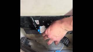
How to confirm: Disconnect the large X1 connector on the transmission. A video showing the general location during a transmission removal can provide context. Per the TSB, physically tug on each wire to ensure the terminal is fully seated; a side load can give a false positive lock. Inspect for any signs of corrosion (green or white powder) or damage to the pins and seals.
Typical fix: Firmly reseat any loose terminals until they click. If corrosion is present, clean the terminals with a specialized contact cleaner and apply dielectric grease before reconnecting. In severe cases, the connector or individual terminals may need to be replaced with a pigtail kit.
Est. part cost: $5-$75 - Poor BCM Power or Ground Connection 🟡 Medium Probability The BCM relies on stable voltage and multiple solid grounds to function. Ground points, particularly G202 which is a key ground for the BCM, can corrode or loosen over time, disrupting the module's operation.
How to confirm: The BCM is located under the driver's side dashboard, to the left of the steering column and generally above the gas pedal. Check that the battery terminals are clean and tight. Use a digital multimeter to verify 12V+ at the BCM's power pins and check for low resistance (<0.5 ohms) between the BCM's ground pins and a known good chassis ground. Service manuals specify two grounds at G202 and another direct to the battery.
Typical fix: Clean and tighten battery terminals and chassis ground points like G202. Repair any compromised wiring to the BCM's multi-pin connectors.
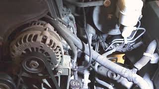
Est. part cost: $0-$20 - Damaged CAN Bus Wiring 🟡 Medium Probability Wiring harnesses can chafe against sharp edges on the engine, transmission, or chassis over time, leading to intermittent shorts or opens in the communication network. TSB #PIC4740E specifically calls out inspecting the harness for chafing near the securing bracket on the passenger side of the transmission bell housing.
How to confirm: Visually inspect the wiring harness, especially where it runs near the transmission bell housing bracket and around the engine. A technician can test CAN bus resistance between Pin 6 and Pin 14 of the OBD-II port. A healthy bus should read approximately 60 ohms. A reading of 120 ohms suggests a break in the circuit or a missing terminating resistor, while a reading near 0 ohms indicates a short circuit.
Typical fix: Repair the damaged section of the wire using solder and heat shrink. Protect the harness from future abrasion using anti-abrasion tape, loom, or by re-routing it away from sharp edges.
Est. part cost: $5-$25 - Faulty Body Control Module (BCM) ⚪ Low Probability → Shop Body Control Module While the module itself can fail internally from heat cycles or component fatigue, it is often misdiagnosed. Water intrusion from a leaking sunroof, windshield cowl, or door seals can drip onto the BCM (located under the dash) and cause corrosion and failure.
How to confirm: This is a last resort after all wiring, connectors, and grounds have been confirmed to be good. A professional scan tool will show the BCM as offline and unresponsive. Another TSB, #PIT4730B, warns that an intermittent network short can make a good BCM appear offline, so careful diagnosis is critical. Physical inspection may reveal 🎬 See this walkthrough for replacing the Body Control Module burn marks or a burnt smell.
Typical fix: Replace the Body Control Module. The new module must be programmed to the vehicle's VIN and specific options using specialized tools. Some vendors sell pre-programmed modules.
Est. part cost: $250-$600
Rare But Worth Checking
- Low Battery Voltage: → Shop Vehicle Battery A weak or failing battery can cause low system voltage, leading to unpredictable behavior from various control modules, including communication dropouts. Always ensure the battery is fully charged and healthy before diagnosing network codes.
- Aftermarket Electronics: Improperly installed remote starters, alarms, or even scan tools can interfere with or crash the CAN bus network, causing communication errors like U0140. One forum user reported that having their EFILive V2 scan tool plugged in consistently caused the Stabilitrak error.
Diagnosis Steps
- Check battery voltage and charge if necessary. A weak battery can cause numerous electrical faults.
- Scan all vehicle modules for stored trouble codes. Note all 'U' codes present, as they point to the scope of the network failure.
- CRITICAL STEP: Following GM TSB #PIC4740E, locate and disconnect the X1 connector at the driver's side of the transmission. Carefully inspect for corrosion and tug each wire to ensure the pins are fully seated in the connector.
- Inspect the wiring harness for any signs of chafing or damage, particularly around the transmission bell housing bracket on the passenger side as specified in the TSB.
- Locate the BCM under the driver's side dash, above the pedals. Inspect the BCM connectors for looseness, corrosion, or signs of water intrusion.
- If wiring and connectors appear intact, use a multimeter to verify good power and ground at the BCM connector. Check for 12V+ on the appropriate pins and less than 0.5 ohms of resistance on ground circuits like G202.
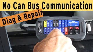
- With the battery disconnected, measure the resistance between Pin 6 (CAN High) and Pin 14 (CAN Low) of the OBD-II port. A healthy CAN bus should read approximately 60 ohms.
- If all wiring and connections are confirmed good, the BCM may be faulty. This should be confirmed by a professional technician before replacement, as programming is required.
Parts You'll Likely Need
- Transmission Connector Terminals/Pigtail
(OEM #88988938)— This is the most likely culprit according to GM TSB #PIC4740E, which points to unseated or damaged pins in the transmission harness connector (X1).
Trusted brands: ACDelco, Dorman
OEM price range: $40-$90
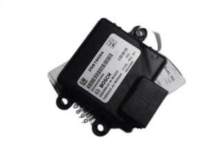
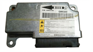
Aftermarket price range: $20-$50 - Body Control Module (BCM)
(OEM #25892622, 25934762, 22860591 (Part numbers vary by year and options, always verify with VIN))— This is the fix if the module itself has failed due to internal faults or water damage, but only after all wiring issues have been ruled out. Requires programming.
Trusted brands: ACDelco (GM Genuine)
OEM price range: $250-$450
Aftermarket price range: $150-$300 (Often refurbished and pre-programmed)
Related Codes That Often Appear With This One
- U0073 — Control Module Communication Bus 'A' Off. This is a general network failure code that often appears with U0140, indicating a system-wide communication problem.
- U0100 — Lost Communication With ECM/PCM. When the network is down, communication is lost with multiple modules, including the Engine Control Module.
- U0101 — Lost Communication With TCM. This code for the Transmission Control Module is very common alongside U0140, especially given the known issue with the transmission X1 connector.
- U0121 — Lost Communication With Anti-Lock Brake System (ABS) Control Module. This often triggers the 'Service Stabilitrak' message.
- C0242, C0561, P0700, P0856 — These are various traction control and transmission-related codes that are logged when those systems lose communication with the BCM or ECM, as detailed in TSB PIC4740E.
Technical Service Bulletins (TSBs) & Recalls
- PIC4740E: Addresses a wide range of communication DTCs (including U0140) and points to the transmission X1 connector pins and harness chafing as the primary cause.
- PIT4730B: Warns that an intermittent network short can make a good BCM appear to be offline, advising thorough wiring diagnosis before module replacement.
Platform-Specific Known Issues
- NHTSA TSB #PIC4740E explicitly calls out unseated terminals in the transmission X1 connector as a primary cause for U0140 and a host of other communication codes on the 2008-2014 CTS.
- NHTSA TSB #PIT4730B describes a scenario where an intermittent short on the high-speed CAN bus can cause the BCM to go offline for an entire ignition cycle, leading a technician to incorrectly diagnose a bad BCM when the fault is in the wiring.
- An owner complaint to the NHTSA (ODI #11533125) for a 2008 CTS lists U0140 along with numerous other communication codes, resulting in a near-accident, highlighting the severity of this network failure.
Mechanic-Grade Diagnostic Values
- High-Speed GMLAN Bus Resistance — expected: 60 ohms (± 5 ohms). Failure: A reading of 120 ohms indicates an open in the bus or a missing terminating resistor. A reading near 0 ohms indicates the CAN High and CAN Low wires are shorted together. A reading less than 60 ohms can indicate a module is shorting the bus.
- BCM Power Supply Voltage — expected: 12.2V - 12.8V (Key On, Engine Off). Failure: Voltage below 12V can cause modules to behave erratically and set communication codes.
- BCM Ground Circuit Resistance — expected: < 0.5 ohms. Failure: Resistance higher than 0.5 ohms indicates a poor ground connection, which can prevent the BCM from operating correctly. Pass 2 mentioned <0.5 ohms, while some generic guides cite <0.1 ohms.
Hidden / Shadow Codes Worth Checking
- U0140 with symptom bytes (e.g., 71, 72): GM often uses two-digit hexadecimal symptom codes to provide more detail. For example, U0073 71 means 'ECU HS Bus Off' and U0073 72 means 'ECU LS Bus Off'. While specific symptom codes for U0140 on this platform are not readily published, their presence on a dealer-level scan tool would provide more granular diagnostic information about the nature of the communication loss (e.g., invalid data, message counter incorrect). (see via GM Tech2 (for pre-2010 models) or GDS2 (Global Diagnostic System 2) for 2010+ models.)
Scan Tool Commands That Help
- GDS2 (Global Diagnostic System 2): Module Diagnostics > BCM > Data Display — To view live data from the BCM, such as power mode, switch inputs (doors, windows), and sensor readings. If the BCM is online but has faulty data, this can help isolate the issue.
- GDS2 (Global Diagnostic System 2): Module Diagnostics > BCM > Control Functions — To perform bidirectional tests by commanding outputs directly (e.g., 'Headlights On/Off', 'Window Down'). If the command works, it confirms the BCM and the wiring to the component are likely good, pointing to a problem with the input (switch) or network communication.
- GDS2 (Global Diagnostic System 2): Vehicle DTC Information > Display DTCs — To perform a full network scan and see which modules are reporting the U0140 code. Seeing if the code is set by one module or many helps determine the scope of the network failure.
Wiring & Ground Locations
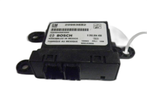
- BCM (Body Control Module) — Located in the center of the dash, often accessed by removing panels under the driver's side dashboard, to the left of the steering column.. This is the module that other computers have lost communication with. Its physical location is important for checking power, ground, and network connections directly at its connectors.
- X1 Connector (Transmission) — The main electrical harness connector on the driver's side of the transmission. It's a large, round, lever-actuated connector.. This is the specific connector identified in TSB #PIC4740E as a primary cause of network communication failures, including U0140, due to loose pins or chafing. The CAN bus wires pass through this connector.
- G200 / G201 — G200 is located in the left (driver's) kick panel area. G201 is in the right (passenger's) kick panel area.. These are major interior ground points for multiple components. While wiring diagrams suggest the BCM's primary grounds are elsewhere, a poor connection at these points can introduce electrical noise or cause issues with other modules on the network, indirectly leading to communication faults.
- G102 — Located on the right front of the engine compartment.. This is a major engine bay ground point. While not a direct BCM ground, poor grounding here can affect the ECM or other engine bay modules, potentially disrupting the entire CAN bus.
- DLC (Data Link Connector) — Under the driver's side dash, typically to the left of the steering column.. This is the access point for all network diagnostics. Pin 6 (CAN High) and Pin 14 (CAN Low) are used to measure the overall resistance of the High-Speed GMLAN bus.
Real Owner Repair Stories
- NHTSA ODI #11533125 (2008 Cadillac CTS) — Vehicle lost power, multiple warning lights, kids were scared. Codes U0100, U0140, U0101, C0242, B0081-0F, B0081-71, B1370-01, B1370-06, U0155-00, U0170-00, P0856-00 were stored.
❌ Tried (didn't work) The complaint does not detail attempted fixes.
✅ What actually fixed it The complaint was filed to report the incident and does not contain the final repair information, but the cluster of codes (U0100, U0101, U0140, C0242, P0856) strongly aligns with the symptoms described in TSB #PIC4740E, pointing to the transmission X1 connector as the likely culprit. [ODI #11533125]
OEM Part Supersession History
13576748, 13580450→13579117— Standard part revision and consolidation by the manufacturer.
Heads up: For the 2011 STS, which shares a similar electrical architecture, compatibility is more limited. However, for the 2011-2014 CTS, these part numbers are generally interchangeable provided the replacement module is properly programmed to the vehicle's VIN.Various→13503724, 13578407, 13579117— These are other known valid part numbers for the BCM in the 2011-2015 CTS range.
Heads up: Regardless of the part number, a replacement BCM (new or used) MUST be programmed by a dealer or a shop with GM-specific software (Techline Connect/SPS) to function. It will not work as a plug-and-play part.
Model Year Variations Within This Range
- 2008-2009: These earlier models are primarily diagnosed using the GM Tech 2 scan tool.
- 2010-2014: GM began phasing in the MDI (Multiple Diagnostic Interface) and GDS2 (Global Diagnostic System 2) software around 2010, with it being fully implemented by 2014. A technician may need GDS2 for full diagnostic capability on these later models, especially for module programming.
Helpful Videos

Used OEM Parts in Stock
New Aftermarket Parts Available


The information in this article is provided for general reference and educational purposes only. Vehicle specifications, procedures, and part compatibility can vary by production date, trim level, and region. Always consult your vehicle's factory service manual and verify part numbers before purchasing or performing repairs. Safety-critical components such as airbags, seat belts, and braking systems should be installed by a qualified professional.
- Cadillac CTS:
- 🧭 Diagnostic Flowchart
- 🎬 Helpful Videos
- 🛍️ Shop This Part
- What's Unique About the 2008-2014 Cadillac CTS
- Symptoms You May Notice
- Most Likely Causes
- Rare But Worth Checking
- Diagnosis Steps
- Parts You'll Likely Need
- Related Codes That Often Appear With This One
- Technical Service Bulletins (TSBs) & Recalls
- Platform-Specific Known Issues
- Mechanic-Grade Diagnostic Values
- Hidden / Shadow Codes Worth Checking
- Scan Tool Commands That Help
- Wiring & Ground Locations
- Real Owner Repair Stories
- OEM Part Supersession History
- Model Year Variations Within This Range
- 🎟️ Get 5% Off