
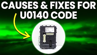
U0140 on 2006-2011 Cadillac STS: Lost Communication With BCM Causes and Fixes
This code means the Body Control Module (BCM) is offline. On the 2006-2011 Cadillac STS, this is frequently caused by a poor connection at the transmission's X1 electrical connector or other intermittent wiring faults, not a failed BCM. Inspecting wiring and connectors, particularly the transmission connector and BCM grounds, is the first step before considering BCM replacement.
- U0140 on a Cadillac STS is most often a wiring or connector problem, not a bad BCM.
- Always inspect the transmission's main electrical connector (X1) first, as recommended by GM.
- Be prepared for a complex electrical diagnosis; this is not typically a simple part swap.
- Do not replace the BCM unless all other possibilities, especially intermittent wiring faults, have been professionally ruled out.
- Symptoms can be erratic and may include flashing dash lights, non-working electronics, and even a no-start condition.
What's Unique About the 2006-2011 Cadillac STS
On many vehicles, a U0140 code might point directly to a failed BCM. However, for the 2006-2011 Cadillac STS and its platform mates, General Motors has issued specific Technical Service Bulletins (TSBs) that highlight wiring and connector problems as the primary culprit. TSB PIC4740E points to a poor connection at the transmission's main electrical connector (X1), which can cause a flood of communication codes, including U0140. Another bulletin, PIT4730B, warns that intermittent shorts in the high-speed GMLAN communication wiring can make the BCM appear offline, even though the module itself is fine. This can happen if the data circuits short to ground or each other twice in less than a second, often when driving over bumps. The BCM will then remain offline for the entire ignition cycle and may take up to 20 minutes to power down and reset. Owners should be very cautious about replacing the BCM before thoroughly checking for these known wiring issues.
Diagnostic Flowchart
Tap your situation to follow the diagnostic path that matches what you're seeing on this vehicle.
Symptoms You May Notice
- Service Stabilitrak message on the Driver Information Center (DIC).
- Door locks cycling on their own while driving.
- Instrument cluster gauges (speedometer, tachometer) freezing or dropping to zero intermittently.
- Power windows, locks, or mirrors not working.
- Interior or exterior lights malfunctioning (staying on, not turning on, or flickering).
- Intermittent no-crank or no-start condition.
- Check Engine Light is on.
- Multiple other warning lights (ABS, Airbag, Traction Control) may be illuminated.
- Keyless entry system fails to work.
- Climate control system behaves unpredictably.
- Replacing the Body Control Module without first performing a thorough diagnosis of the vehicle's wiring and connectors. TSBs strongly advise against this, as the fault is often external to the BCM.
Most Likely Causes
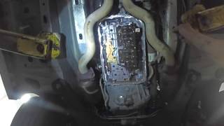
- Loose or Corroded Transmission X1 Connector Terminals 🔴 High Probability → Shop HVAC Wiring Harness Connector Terminal This is a documented issue in GM TSB #PIC4740E. The transmission connector is exposed to the elements and vibration, leading to poor pin fitment over time, which disrupts the entire vehicle communication network that passes through it.
How to confirm: Visually inspect the large X1 electrical connector on the transmission. Disconnect it and check for any signs of corrosion, moisture, or backed-out/loose terminal pins. A wiggle test on the connector while the car is running may trigger the symptoms. Per the TSB, you should carefully tug on each wire to ensure the pins are fully seated.
Typical fix: Clean the connector terminals with electrical contact cleaner and apply dielectric grease. If terminals are loose or damaged, they may need to be re-pinned or the connector pigtail may need to be repaired.
Est. part cost: $10-$50 - Intermittent Short or Open in CAN Bus Wiring 🟡 Medium Probability TSB #PIT4730B specifically notes that intermittent shorts in the high-speed GMLAN data circuits (circuits 2500 & 2501) are a known cause for the BCM appearing offline. These issues are often triggered by driving over bumps or rough roads, causing the harness to rub against a chassis component.
How to confirm: This requires advanced diagnostics. A technician will use a multimeter to check for correct resistance (around 60 ohms) between pins 6 and 14 of the OBD-II port with the battery disconnected. They will also perform a 'wiggle test' on the wiring harness while monitoring network status to find the intermittent fault.
Typical fix: Locate the damaged section of the wiring harness and repair the broken or shorted wire using DuraSeal splice sleeves. Pay attention to areas where the harness passes through the firewall or near sharp metal edges.
Est. part cost: $5-$25 - Poor BCM Power or Ground Connection ⚪ Low Probability Corrosion at chassis ground points is a common issue on aging vehicles. The BCM has specific ground points (e.g., G103, G302) that can become loose or corroded, starving the module of the stable ground it needs to communicate. A weak or failing battery can also cause low voltage issues that trigger communication codes.
How to confirm: Disconnect the negative battery terminal. Locate the BCM ground points (a key ground, G103, is on the cowl above the brake booster) and inspect for corrosion or looseness. Use a multimeter to verify stable battery voltage (12.2-12.8V with ignition on) at the BCM's power input pins and check for near-zero resistance (< 0.1 Ω) between the BCM's ground pins and a known-good chassis ground.
Typical fix: Clean and tighten the ground connection (sand the metal to bare, apply dielectric grease). Repair the power feed wire or fuse connection. Have the battery load tested and replace if weak.
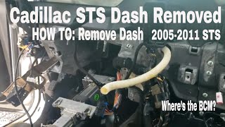
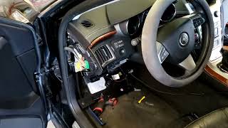
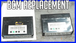
Est. part cost: $1-$20 - Faulty Body Control Module (BCM) ⚪ Low Probability → Shop Body Control Module While the BCM can fail, it is less common than the wiring issues described in TSBs. Water intrusion from a leaking seal or internal component failure can cause the module to go offline permanently. The BCM on the STS is located on the right-hand side of the dash, often behind the glove compartment.
How to confirm: This is a process of elimination. If all wiring, connectors, power, and grounds to the BCM have been tested and confirmed to be good, and a scan tool still cannot communicate with the BCM, the module itself is the likely point of failure.
Typical fix: Replace the Body Control Module. The new module will require programming to the vehicle's VIN and specific options using dealer-level software like Techline Connect. After installation, a 'Setup SDM Primary Key in BCM' procedure is often required to sync with the airbag module.
Est. part cost: $250-$500
Rare But Worth Checking
- Faulty aftermarket electronics (remote start, alarm, stereo) improperly spliced into the CAN bus network, causing interference.
Diagnosis Steps
- Check battery voltage first. A weak or failing battery can cause a host of communication issues. Voltage should be ~12.6V with the engine off and 13.7-14.7V when running.
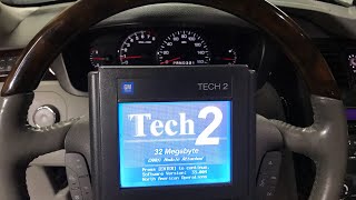
- Scan all vehicle modules for stored trouble codes. Note all 'U' codes present, as they can point to the source of the network failure.
- Carefully follow the advice in TSB #PIC4740E: Disconnect and inspect the transmission X1 connector for any loose, corroded, or damaged terminals. Clean with contact cleaner and apply dielectric grease. Repair as needed.
- If the transmission connector is okay, follow the advice in TSB #PIT4730B: Investigate an intermittent wiring fault. Visually inspect the main wiring harnesses, especially where they might rub against the chassis or engine components.
- With the battery disconnected, check CAN bus resistance. Use a multimeter on pins 6 (CAN High) and 14 (CAN Low) of the OBD-II port. A healthy network should read approximately 60 Ohms. Readings of 120 Ohms suggest a break in the circuit or a missing terminating resistor, while readings near 0 Ohms indicate a short between the two CAN lines.
- Perform a 'wiggle test' on the harness sections leading to the BCM and at the OBD-II port while monitoring network status with a scan tool.
- Disconnect the negative battery terminal. Locate and inspect the primary BCM ground connections (e.g., G103 on the cowl) for tightness and corrosion. Clean and tighten as necessary.
- Verify the BCM has proper power and ground connections using a multimeter directly at the BCM connector. Check for battery voltage (approx. 12.6V) at the appropriate power pins and less than 0.1 Ohms of resistance on the ground circuits.
- If all wiring, connectors, power, and grounds are confirmed to be good, and the BCM is still offline, then suspect a faulty BCM.
Parts You'll Likely Need
- Connector Terminals / Pigtail — To repair the transmission X1 connector, which is a common failure point according to TSB PIC4740E.
Trusted brands: ACDelco
OEM price range: $20-$60
Aftermarket price range: $10-$40 - Body Control Module (BCM)
(OEM #15262719, 15816761, 15884958, 15934303, 25857315, 25892622)— This is the part to replace ONLY after all wiring and connection issues have been ruled out. Part number varies by year and options. A replacement requires VIN programming.
Related Codes That Often Appear With This One
- U0073 — Control Module Communication Bus 'A' Off. This is a general network code often set alongside U0140 due to the same underlying wiring fault, as noted in TSB PIC4740E.
- U0100 — Lost Communication with ECM/PCM. A network disruption can affect multiple critical modules, and this code is explicitly mentioned in TSB PIC4740E.
- U0121 — Lost Communication with Anti-Lock Brake System (ABS) Control Module. The ABS module is on the same high-speed network and its communication is often disrupted by the same faults. It is also listed in TSB PIC4740E.
- P0700 — Transmission Control System (TCS) Malfunction. This code is often triggered when the transmission connector issue (per TSB PIC4740E) is the root cause, as it directly impacts TCM communication.
Technical Service Bulletins (TSBs) & Recalls
- PIC4740E: Mentions that various communication codes, including U0140, can be caused by loose or poor-fitting terminals in the transmission X1 connector.
- PIT4730B: Details how intermittent shorts on the high-speed GMLAN circuits (2500 & 2501) can cause the BCM to appear offline and warns technicians not to replace the BCM without first diagnosing for intermittent electrical faults.
- 07-08-47-004D: Informs technicians that the BCM can be internally damaged if a ground path is removed while the module is powered. It mandates disconnecting the negative battery cable before servicing BCM grounds.
Platform-Specific Known Issues
- Per TSB PIC4740E, the transmission X1 connector is a known weak point that can cause U0140 and many other communication codes.
- Per TSB PIT4730B, the high-speed GMLAN wiring is susceptible to intermittent shorts that can take the BCM offline for an entire ignition cycle, mimicking a failed module.
- Per TSB 07-08-47-004D, it is critical to disconnect the negative battery terminal before servicing any BCM ground paths to prevent damaging the module.
Mechanic-Grade Diagnostic Values
- CAN Bus Network Resistance — expected: Approximately 60 Ω. Failure: 120 Ω indicates an open in the circuit or a missing terminating resistor. Near 0 Ω indicates a short between the CAN High and CAN Low wires.
- BCM Battery Voltage at Connector — expected: 12.2 - 12.8 V with ignition on. Failure: Low or no voltage indicates a problem with the power feed wire or fuse.
- BCM Ground Resistance at Connector — expected: < 0.1 Ω. Failure: Higher resistance indicates a poor ground connection, which can cause module malfunction.
Scan Tool Commands That Help
- GDS2 / Tech2: Setup SDM Primary Key in BCM — This procedure is required after replacing the BCM to synchronize it with the Sensing and Diagnostic Module (airbag module). Failure to perform this step will typically leave the airbag warning light illuminated.
Wiring & Ground Locations
- G103 — Located at the left rear of the engine compartment on the cowl, above the brake booster.. This is a primary ground point for multiple critical modules, including the Body Control Module (BCM), Instrument Panel Cluster (IPC), and the Data Link Connector (DLC). Corrosion or looseness here can directly cause the BCM to lose communication.
- G302 — Located under the center console at the rear, below the rear fuse block.. This ground serves the radio amplifier. While not a direct cause for U0140, issues with modules on the network can sometimes create unpredictable communication faults.
- G402 — In the rear compartment, to the rear of the left rear shock tower.. This is the ground for the Rear Integration Module (RIM). A fault with the RIM or its ground could potentially disrupt network communications.
- SP200 (Splice Pack) — Located in the left side of the instrument panel, near the steering column, taped to the instrument panel harness.. Splice packs are junction points where multiple CAN bus wires meet. Corrosion or a poor connection inside this splice pack can take down the entire network, isolating the BCM and other modules.
- Transmission Connector X1 — The main electrical harness connector on the transmission housing.. As per TSB PIC4740E, this is a primary failure point. The GMLAN network wires pass through this connector, and poor pin fitment can disrupt communication for many modules, including the BCM, ECM, and TCM.
OEM Part Supersession History
Multiple, including 15884958, 15934303, 25857315→25892622— Part consolidation and updates over time. 25892622 is a common service replacement for a wide range of GM vehicles from this era, including the STS, CTS, Acadia, and others.
Heads up: While physically compatible, the module must be programmed with the vehicle's specific VIN and options. After installation, it may require a scan tool procedure to sync with the airbag module (SDM).
Model Year Variations Within This Range
- 2008-2011: The 2008 model year introduced a significant refresh, including a new standard direct-injected 3.6L V6 engine with 302 hp and a six-speed automatic transmission. New technology options like Lane Departure Warning and Side Blind Zone Alert were added, which communicate via the CAN bus and could be affected by a U0140 fault.
- 2011: For the final model year, the 4.6L Northstar V8 engine option was discontinued. All 2011 STS models came with the 3.6L V6.
Helpful Videos

![How To Test CAN BUS With A Multimeter [CAN Bus Resistance Check] Mechanic Mindset](https://img.youtube.com/vi/JPE42HSJxAk/mqdefault.jpg)


We Have This Part in Stock

The information in this article is provided for general reference and educational purposes only. Vehicle specifications, procedures, and part compatibility can vary by production date, trim level, and region. Always consult your vehicle's factory service manual and verify part numbers before purchasing or performing repairs. Safety-critical components such as airbags, seat belts, and braking systems should be installed by a qualified professional.
- Cadillac STS:
- 🧭 Diagnostic Flowchart
- 🎬 Helpful Videos
- 🛍️ Shop This Part
- What's Unique About the 2006-2011 Cadillac STS
- Symptoms You May Notice
- Most Likely Causes
- Rare But Worth Checking
- Diagnosis Steps
- Parts You'll Likely Need
- Related Codes That Often Appear With This One
- Technical Service Bulletins (TSBs) & Recalls
- Platform-Specific Known Issues
- Mechanic-Grade Diagnostic Values
- Scan Tool Commands That Help
- Wiring & Ground Locations
- OEM Part Supersession History
- Model Year Variations Within This Range
- 🎟️ Get 5% Off