
U1000 on 2002-2007 Buick Rendezvous: Causes and Fixes for Communication Loss
On a 2002-2007 Buick Rendezvous, code U1000 almost always means a module has failed or a wire is broken on the Class 2 data network. The most common culprits are a faulty Instrument Panel Cluster or a broken data wire. Diagnosis is complex, but unplugging modules one-by-one at the main splice pack (SP205) can help isolate the issue.
- U1000 on a Buick Rendezvous is a network communication error, not an engine part failure.
- The most likely cause is a faulty Instrument Panel Cluster, a very common issue on these vehicles.
- Diagnosis is complex and best left to a professional with GM-specific diagnostic tools.
- A simple first check is to test the battery, as low voltage can cause communication glitches.
- Do not replace the main engine computer (ECM/PCM); it is almost never the cause of this code.
What's Unique About the 2002-2007 Buick Rendezvous
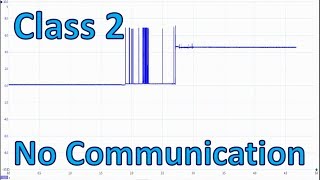
The 2002-2007 Buick Rendezvous uses an older GM communication protocol called 'Class 2 Serial Data' (SAE J1850 VPW). Unlike modern CAN bus systems with two wires, this is a single-wire network (typically a dark green wire on pin 2 of the DLC). This design means that if any single module or the wire itself gets shorted, it can bring down the entire network, causing a cascade of seemingly unrelated electrical problems. Failures of the Instrument Panel Cluster are particularly common on this platform and are a frequent cause of this code. Another key diagnostic point is Splice Pack 205 (SP205), a junction box where the data lines from many modules meet, which is conveniently located behind the driver's side dash end cap panel.
Symptoms You May Notice
- Check Engine Light or 'Service Vehicle Soon' light is on
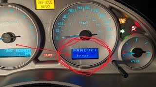
- Gauges on the instrument cluster stop working, freeze, or behave erratically
- Vehicle may not start (no-crank condition)
- Security light may be flashing
- Radio, HVAC (climate control), or other interior electronics may not work
- Odometer displays an error message or is blank
- Stalling
- Multiple, seemingly unrelated warning lights (ABS, Traction Control, AWD Disable) may appear
- Replacing the ECM/PCM. The U1000 code is almost never caused by a bad Engine Control Module. The ECM is the one reporting the problem, not the source of it.
- Replacing random sensors. This is a network communication issue, not a sensor failure. Other codes may be present as a result of the U1000, but fixing the communication problem is the first step.
Most Likely Causes
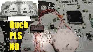
- Faulty Instrument Panel Cluster (IPC) 🔴 High Probability → Shop Instrument Cluster The stepper motors and internal power supplies on these clusters are a well-documented, common failure point for this generation of GM vehicles. An internal short in the cluster's electronics can corrupt or short out the entire Class 2 data bus.
How to confirm: With a capable scan tool, check if the IPC is offline. A simpler method is to unplug the main connector from the back of the instrument cluster. If other vehicle systems (like the radio or HVAC) start working again, the cluster is the faulty component pulling the network down. Another method is to disconnect the IPC branch from splice pack SP205 to see if communication is restored to the rest of the vehicle.
Typical fix: The cluster must be either replaced or, more commonly, sent to a specialist for rebuilding. 🎬 Watch: How to repair the instrument cluster yourself Rebuilding is often preferred as it retains the original mileage and VIN programming and comes with a lifetime warranty from many vendors.
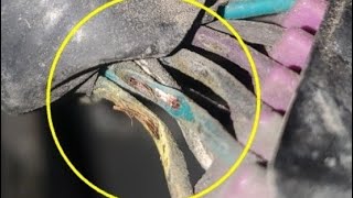
Est. part cost: $120-$300 for a rebuild service. - Broken or Shorted Class 2 Serial Data Wire 🟡 Medium Probability Over time, wires can chafe, corrode, or break, especially in areas where the harness passes through the firewall, into doors, or near moving parts. Splice packs, where multiple data wires join, are also common points of failure due to corrosion. A user on 2CarPros.com reported a U1000 code after an owner attempted a radio install and created a short.
How to confirm: This requires advanced diagnostics. A technician will use a wiring diagram and an oscilloscope or multimeter to check for the 0-7 volt data signal at various points, starting at the Data Link Connector (DLC) 🎬 See how to test data wires with a lab scope and moving to splice packs (like SP205) and individual modules. A lack of signal or a signal that is stuck high (short to power) or low (short to ground) indicates a wiring fault.
Typical fix: Locate the break or short in the wire (often a dark green wire) and repair the damaged section. Check common chafe points in the driver's side door jamb and under the dash near the steering column.
Est. part cost: $5-$20 for wire and connectors - Faulty Body Control Module (BCM) ⚪ Low Probability → Shop Body Control Module The BCM controls many body and security functions and acts as a gateway for the Class 2 network. Like any electronic module, it can fail due to age, moisture, or voltage spikes, causing a host of strange electrical issues.
How to confirm: Using a process of elimination, if the IPC and wiring check out, the BCM becomes a suspect. A technician would unplug the BCM to see if network communication is restored to other modules. A scan tool will also show the BCM as offline or report codes like U1016 (Loss of Communication with BCM).
Typical fix: Replace the BCM. A new or used BCM will require programming with a GM Tech 2 or equivalent scan tool to match the vehicle's VIN and options.
Est. part cost: $100-$300 for a used or remanufactured unit - Weak or Failing Battery ⚪ Low Probability → Shop Vehicle Battery Low system voltage during cranking can cause modules to fail to initialize properly, leading to temporary communication codes. While often a trigger, it's less likely to be the root cause if the code persists after the engine is running.
How to confirm: Test the battery's voltage and load capacity. A healthy battery should be above 12.4 volts at rest and should not drop below ~10 volts during cranking. Check for corroded or loose battery terminals.
Typical fix: Replace the vehicle's battery.
Est. part cost: $150-$250
Rare But Worth Checking
- Faulty Radio or OnStar Module: The factory radio and the OnStar module (VCIM) are both nodes on the Class 2 network. If they internally short, they can bring down communication. If you have aftermarket electronics installed, especially a radio, start your diagnosis there. Unplugging the suspect module is the easiest way to check. A bad radio install is a known cause of this code.
- Aftermarket Accessories: Improperly installed remote starters, alarms, or audio equipment can interfere with or damage the Class 2 data line, causing this code. Always suspect aftermarket additions first when troubleshooting network issues.
- Faulty HVAC Control Module: The HVAC control head is another module on the Class 2 network. Though less common to fail in a way that brings down the network, it is a possibility. Unplugging it during the diagnostic process can rule it out.
Diagnosis Steps
- Connect a professional scan tool capable of reading GM-specific codes from all modules.
- Attempt to communicate with every module on the vehicle (ECM, BCM, IPC, Radio, HVAC, etc.). Make a list of which modules are not responding.
- If many modules are offline, the problem is likely network-wide. Start by checking the battery and charging system to rule out low voltage. Ensure battery terminals are clean and tight.
- Inspect the Class 2 data line (Pin 2, a dark green wire) at the Data Link Connector (DLC) for a signal. A healthy, active Class 2 network will show a fluctuating 0-7 volt square wave on an oscilloscope. A multimeter should show fluctuating voltage.
- Locate the main data line splice pack, SP205. It is located behind the trim panel on the driver's side of the dashboard, easily accessible with the driver's door open.
- Remove the shorting bar from SP205. 🎬 Watch: Step-by-step Class 2 network diagnostics case study This isolates all the network branches.
- With the shorting bar removed, use a jumper wire to connect the main data line from the DLC to each individual pin in SP205 one at a time, attempting to communicate with the corresponding module using the scan tool. This helps identify which module or branch is causing the network to crash.
- If a specific module's circuit is identified as the problem, unplug that module directly. If unplugging it restores communication to the rest of the network, that module is faulty and needs to be repaired or replaced.
- If no single module is at fault, the issue is likely in the wiring harness itself. Visually inspect the harness for damage, corrosion, or poor connections, paying close attention to the dark green data wire, especially in door jambs and under the dash.
Parts You'll Likely Need
- Instrument Panel Cluster (Rebuild Service)
(OEM #10330864, 15224899, 10387094)— This is the most common module to fail and cause a U1000 code on this vehicle. A rebuild replaces the faulty internal components like stepper motors and power supply circuits. Multiple vendors like Module Master and Automotive Circuit Solutions offer this service.
Related Codes That Often Appear With This One
- U-series codes (e.g., U1001, U1301, U1016, U1064) — Multiple U-codes stored in different modules all point to a general loss of communication on the Class 2 network. Each code may indicate which specific module has lost communication with another.
- B-series or P-series codes — If the BCM or ECM loses communication with another module, it may set codes related to the functions it can no longer control or monitor. For example, if the ECM can't talk to the IPC, you may get a P-code for a sensor reading that is normally displayed on the dash.
Platform-Specific Known Issues
- The instrument panel clusters on 2002-2007 GM vehicles, including the Rendezvous, are known to have high failure rates due to faulty stepper motors and power supply circuits.
- Splice Pack SP205, the main junction for the Class 2 data line, is a key diagnostic point. It is conveniently located behind the driver's side dash end cap panel, making network branch isolation easier than on some other vehicles.
- A forum user on GM Forum detailed a diagnostic process for a similar vehicle, checking continuity from the ECM to SP205 as a primary step.
Mechanic-Grade Diagnostic Values
- Class 2 Data Line (J1850 VPW) Voltage — expected: A fluctuating square wave signal between 0V and +7V with the key on. The bus idles low (0V).. Failure: A signal stuck high (short to power), stuck low (short to ground), or a voltage fixed at an intermediate level (e.g., 4V) indicates a network fault.
- Class 2 Data Line High/Low Thresholds — expected: The high logic level is typically above +3.5V, and the low logic level is below that. The peak voltage is around 7V.. Failure: If the voltage does not cleanly switch between the high and low states, it can indicate a weak driver in a module or a wiring issue.
Scan Tool Commands That Help
- GM Tech 2: Module Communication Test / Network Health Check — This function polls all expected modules on the Class 2 network and reports which ones are not responding. This is the first step to see the scope of the communication failure and identify which modules are offline.
- GM Tech 2: BCM/PCM Reprogramming — After replacing a Body Control Module (BCM) or Powertrain Control Module (PCM), it must be programmed with the vehicle's specific VIN and option configuration. A U1000 code can be set if a new, unprogrammed module is installed.
Wiring & Ground Locations
- SP205 — Behind the trim panel on the driver's side of the dashboard, accessible with the driver's door open.. This is the central junction for the Class 2 data line. Isolating circuits here is the primary method for diagnosing which module or wiring branch is causing the network to fail.
- G201 — On the left side of the dash, on the underside of the cross-car beam.. This is a primary interior ground point. It grounds the BCM, IPC, Radio, and the Data Link Connector itself. A poor connection at G201 can cause multiple modules to lose communication and set a U1000.
- G301 — On the left 'B' pillar, under the seat belt anchor.. This ground serves various components, and while less likely to be the primary cause, poor grounds in the vehicle can introduce electrical noise that disrupts the Class 2 network.
- G302 — On the right 'B' pillar, under the seat belt anchor.. Similar to G301, ensuring all major body grounds are clean and tight is a crucial step in diagnosing any network communication issue.
- C305 — On the floor, just to the rear of the driver's seat.. This connector is a known point for corrosion due to water intrusion. An intermittent connection here can cause a host of seemingly unrelated electrical gremlins and communication codes.
Real Owner Repair Stories
- GMTNation forum user (2006 Buick Rainier 4.2L (similar platform and Class 2 system)) — No crank, no start. No communication with PCM via Tech 2 scanner. Radio and HVAC lights were out.
❌ Tried (didn't work) Swapping the PCM., Checking PCM grounds., Checking signals at the splice packs.
✅ What actually fixed it A very small cut was found in the orange 12V battery wire going to the PCM (pin 20 on connector C1). Repairing this wire restored power to the PCM and resolved the no-communication issue. - 2CarPros forum user (2002 Buick Rendezvous AWD) — U1000 code present, 'AWD Disable' message on the instrument cluster.
❌ Tried (didn't work) Replacing the PCM with one from a FWD model., Programming a new, correct PCM with a Tech2 and performing the VTD (Vehicle Theft Deterrent) relearn.
✅ What actually fixed it The initial problem was caused by the owner creating a short circuit while attempting to change the radio, which damaged the original PCM. The story highlights that even after replacing the damaged module, the U1000 code can persist if there is still an underlying wiring issue or if another module was damaged. The final fix was not explicitly stated, but the cause was confirmed to be the radio installation short. - NHTSA ODI #10186630 — An owner of a similar GM platform (Regal) reported a no-crank/no-start condition where the shifter was locked in park. Diagnostic trouble codes U1000 and U1016 were set, accompanied by intermittent instrument panel cluster behavior.
OEM Part Supersession History
10329374→15234888, 88999104— Standard part evolution and updates by the manufacturer.
Heads up: BCMs for 2002-2005 models may differ from 2006-2007 models. Always verify the part number for your specific year and VIN before purchasing. A replacement BCM requires programming to the vehicle.
Model Year Variations Within This Range
- 2002-2005 vs 2006-2007: The standard 3.4L V6 engine was replaced by a 3.5L V6 in 2006. A black-faced instrument cluster replaced the previous silver one in 2005/2006. For 2006, Buick introduced a suite of sound-deadening features called 'QuietTuning'. While not directly related to U1000, these changes mean wiring harnesses and module software could have minor differences. The BCM part numbers also appear to change around the 2005/2006 model year.
- 2004+: An optional 3.6L V6 engine became available. OnStar became standard equipment, adding another module to the Class 2 network that could potentially fail and cause a U1000 code.
Diagnostic Flowchart
Other Known Issues on This Vehicle
Issues unrelated to this code that are worth knowing about as an owner of this generation:
- Leaking Lower Intake Manifold (LIM) Gaskets (3.4L V6) 🔴 High — Extremely common. The original plastic/silicone gaskets degrade from exposure to Dex-Cool coolant, typically failing between 60,000 and 120,000 miles. Can lead to coolant mixing with oil and catastrophic engine damage if ignored. (Ref: TSB #03-06-01-010C)
- Failing Wheel Bearing / Hub Assemblies 🟠 Medium — Common failure, often starting around 75,000-100,000 miles. Symptoms include a humming/grinding noise from the wheels and an illuminated ABS light, as the ABS sensor is integrated into the hub.
- Faulty Transmission Pressure Control Solenoid (4T65-E) 🟠 Medium → Shop Transmission Assembly — A common issue causing harsh/erratic shifting, slamming into gear, or feeling like the transmission is slipping.
- AWD System Disabled Light 🟡 Low — Often caused by a failing wheel speed sensor (part of the hub assembly) or a broken wire leading to the sensor. The system disables the AWD as a precaution when it can't get an accurate speed reading from all four wheels.
- Premature Air Conditioning System Failure 🟠 Medium — Owners report premature failure of A/C components, particularly the condenser, leading to expensive repairs.
Used vs. New Parts: Buying Guide for This Vehicle
When a used part is the smart pick: A used Instrument Panel Cluster (IPC) or Body Control Module (BCM) can be a cost-effective option, provided you can verify the part number matches and you have access to a GM Tech 2 or equivalent scan tool for programming.
Donor-vehicle mileage cap: roughly under 120000 miles for the part to have meaningful remaining life.
What to inspect on the donor part:
- For an IPC, check the lens for deep scratches or hazing.
- For any module, inspect the connector pins for any signs of corrosion, moisture, or damage.
- If possible, get the VIN of the donor vehicle to help with compatibility checks.
- Avoid parts from vehicles with signs of flood or fire damage.
Aftermarket brands forum-validated for this vehicle:
- For IPC repair: Automotive Circuit Solutions, Module Master, Auto Tech Rescue, and ISS Automotive are frequently mentioned as reputable rebuild services.
Brands owners have reported issues with on this vehicle:
- Be cautious of no-name, pre-programmed BCMs from online marketplaces without a clear warranty or return policy, as programming is critical and often done incorrectly.
Real Owner Stories
Aggregated from forums and TSBs cited above. Mileages and costs reflect what owners reported in those sources.
2002 Buick Rendezvous
Symptoms: Owner reported a U1000 code appearing immediately after attempting a radio installation.
What fixed it: The issue was traced to a short circuit created during the radio installation process that disrupted the Class 2 data bus.
Source hint: 2CarPros.com thread titled '2002 Buick Rendezvous DTC U1000'
2005 Buick Rendezvous 3.6L
Symptoms: Owner was seeking the location of specific network components to diagnose communication issues.
What fixed it: The diagnostic process involved checking continuity from the ECM to the main splice pack (SP205) to isolate the communication break.
Source hint: GM Forum thread '2005 buick rendezvous 3.6 location'
Documented NHTSA Reports
Symptoms: NHTSA ODI #10186630 describes a situation where the engine would not crank or start, the shifter was locked in park, and various instrument panel cluster functions were intermittent.
What fixed it: Diagnostic trouble codes U1000, U1016, B1422, B2957, and B2958 were set during this failure event.
Related OBD-II Codes
Frequently Asked Questions
Where is the main data line junction located on my Buick Rendezvous for diagnosing U1000?
My 2002-2007 Rendezvous has a U1000 code and the gauges are freezing. Is there a common part failure?
Should I replace or rebuild my instrument cluster to fix this communication error?
Can a bad battery cause a U1000 code on this vehicle?
Is there a specific TSB for the common engine issues that might appear alongside electrical codes?
What color wire should I look for when testing the Class 2 Serial Data network?
Helpful Videos
We Have This Part in Stock

The information in this article is provided for general reference and educational purposes only. Vehicle specifications, procedures, and part compatibility can vary by production date, trim level, and region. Always consult your vehicle's factory service manual and verify part numbers before purchasing or performing repairs. Safety-critical components such as airbags, seat belts, and braking systems should be installed by a qualified professional.
- Buick Rendezvous:
- 🧭 Diagnostic Flowchart
- 🎬 Helpful Videos
- 🛍️ Shop This Part
- What's Unique About the 2002-2007 Buick Rendezvous
- Symptoms You May Notice
- Most Likely Causes
- Rare But Worth Checking
- Diagnosis Steps
- Parts You'll Likely Need
- Related Codes That Often Appear With This One
- Platform-Specific Known Issues
- Mechanic-Grade Diagnostic Values
- Scan Tool Commands That Help
- Wiring & Ground Locations
- Real Owner Repair Stories
- OEM Part Supersession History
- Model Year Variations Within This Range
- Other Known Issues on This Vehicle
- Used vs. New Parts: Buying Guide for This Vehicle
- Real Owner Stories
- 2002 Buick Rendezvous
- 2005 Buick Rendezvous 3.6L
- Documented NHTSA Reports
- Related OBD-II Codes
- Frequently Asked Questions
- 🎟️ Get 5% Off