
U1000 on 2004-2007 Cadillac CTS: Causes and Fixes for Network Communication Loss
On a 2004-2007 Cadillac CTS, code U1000 indicates a loss of communication on the Class 2 data network. A GM Technical Service Bulletin (#PIC5460B) points to a wiring issue near the Engine Control Module (ECM) as a primary cause. The fix often involves inspecting and repairing this wiring, but can also be a faulty module, poor grounds, or issues with aftermarket equipment.
- U1000 on a 2004-2007 CTS is a network communication error, not a specific part failure.
- Always inspect the wiring harness near the Engine Control Module first, as this is a known failure point documented in a GM TSB.
- Do not replace expensive modules like the ECM or BCM without confirming they are the source of the problem through systematic diagnosis.
- This is a complex diagnostic task that typically requires a professional-grade scan tool and electrical troubleshooting skills.
- Symptoms can be severe, including a no-start or stalling condition, so the vehicle should not be driven until repaired.
What's Unique About the 2004-2007 Cadillac CTS

The 2004-2007 Cadillac CTS belongs to an era of GM vehicles that heavily relied on the older Class 2 (J1850 VPW) communication protocol, a single-wire network. Unlike modern, more robust CAN bus systems, this Class 2 network can be sensitive; a problem with a single module or a short in one wire can disrupt communication across multiple vehicle systems, leading to a cascade of error codes and confusing symptoms. A specific Technical Service Bulletin for this platform, #PIC5460B, highlights a known vulnerability in the wiring harness near the Engine Control Module, making it a critical first place to inspect. The ECM itself is located behind the driver-side front wheel well liner, a location that can expose its connectors to moisture and corrosion if the liner is damaged.
Diagnostic Flowchart

Tap your situation to follow the diagnostic path that matches what you're seeing on this vehicle.
Symptoms You May Notice

- No-start or no-crank condition. 🎬 Watch a real-world diagnosis of an intermittent no-start condition.
- Check Engine Light or Service Vehicle Soon message is on.
- Key may become stuck in the ignition.
- Erratic gauge behavior or loss of instrument panel cluster lights.
- Loss of communication with the scan tool for one or more modules.
- Other warning lights, such as ABS or Traction Control, may illuminate.
- Electrical glitches like windows, radio, or climate control malfunctioning.
- Delayed instrument cluster power-up; dash may seem dead for 5-10 seconds after key-on before coming to life.
- Replacing the Engine Control Module (ECM) without first inspecting the wiring. The TSB clearly indicates that wiring is a very common cause, and an expensive ECM replacement will not fix a broken wire.
- Replacing the battery without checking for a parasitic draw from a faulty module. A module that fails to 'sleep' can drain the battery, and the resulting low voltage causes the U1000 code, but the root cause is the faulty module, not the battery itself.
Most Likely Causes

- Damaged or Corroded Wiring Harness 🔴 High Probability A manufacturer TSB (#PIC5460B) specifically identifies the Ignition 1 Power Feed (circuit 5290) or the Class 2 data line (circuit 1807) wiring to the Engine Control Module (ECM) as a primary cause. The harness is exposed to heat and vibration, and can chafe against engine or chassis components. The ECM's location behind the wheel well liner also makes its connectors vulnerable to water intrusion and corrosion.
How to confirm: Visually inspect the wiring harness leading to the ECM for any signs of chafing, breaks, or corrosion. Use a multimeter to check for continuity and proper voltage on the Class 2 data line (typically a Dark Purple wire on Pin 58 of the C1 connector at the ECM) and verify power/ground at the affected modules per TSB #PIC5460B.
Typical fix: Repairing the damaged section of the wire or connector. This involves cutting out the bad section, splicing in new wire, and protecting it with heat shrink tubing and loom.
Est. part cost: $5-$25 - Faulty Control Module 🟡 Medium Probability Any of the 15+ modules on the Class 2 network (ECM, BCM, TCM, radio, etc.) can fail internally. When a module fails, it can either stop communicating entirely or 'scream' on the network with garbage data, preventing other modules from talking. The Body Control Module (BCM) is a frequent failure point, causing widespread electrical issues.
How to confirm: Using a professional scan tool, perform a module 'roll-call' to see which modules are not responding. A common diagnostic technique is to unplug modules one by one from the Class 2 network until communication is restored to the other modules. If unplugging the radio, for example, allows the ECM and BCM to communicate again, the radio is the faulty component.
Typical fix: Replace the failed module. Note that many modules, like the ECM or BCM, require programming with a GM-specific tool after installation.
Est. part cost: $200-$1000+ - Poor Battery Voltage or Bad Grounds ⚪ Low Probability → Shop Vehicle Battery While not specific to this platform, low system voltage from a weak battery or corroded ground straps can cause unpredictable electronic issues, including communication faults. A voltage drop during startup is a common trigger for intermittent U-codes. Key ground points like G101 (engine block) and G103 (cowl) are critical for module communication.
How to confirm: Test the battery's state of charge and its ability to hold a load. Inspect and clean the main battery terminals, chassis ground points (especially G101 and G103), and engine ground straps for corrosion or looseness.
Typical fix: Clean battery terminals and ground points. If the battery is weak, replace it.
Est. part cost: $10-$250
Rare But Worth Checking
- Improperly Installed Aftermarket Equipment: Aftermarket radios, remote starters, or alarms that are not installed with the correct interface adapter can interfere with or damage the Class 2 data line, causing widespread communication issues. The factory radio is an active module on the network; simply replacing it without the proper adapter can cause a no-start condition as other modules fail to see it on the network.
- Faulty OnStar Module (VCIM): On related GM platforms like the Cadillac STS, a failing OnStar module is a very common cause of network communication codes. Though less documented for the CTS specifically, if other causes are ruled out, unplugging the OnStar module is a valid diagnostic step to see if network communication is restored.
Diagnosis Steps
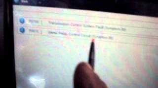
- Scan all available modules for DTCs. Note which modules are setting U1000 or other 'Lost Communication' codes.
- Using a professional scan tool (like a GM Tech 2), attempt to communicate with each module individually to see which ones are offline.
- Check the battery voltage and ensure it is stable and above 12.4V. A weak battery is a frequent cause of intermittent communication codes.
- Inspect the main battery terminals and primary chassis/engine grounds for corrosion and tightness. Specifically check ground G101 on the engine block and G103 on the cowl.
- Following TSB #PIC5460B, carefully inspect the wiring harness connected to the Engine Control Module (ECM) for any signs of chafing, damage, or corrosion. Pay special attention to the Ignition 1 Power Feed (Circuit 5290) and the Class 2 data wire (Circuit 1807, typically a dark purple wire).
- If a specific module is not communicating, check for power and ground at that module's connector.
- If multiple modules are offline and wiring appears intact, begin unplugging non-essential modules (e.g., radio, OnStar module, seat module) one at a time to see if communication is restored to the rest of the network.
- If the fault persists, an oscilloscope can be used on the Class 2 data line (OBD-II port, Pin 2) to check for a clean 0-7 volt square wave signal. A flat line indicates an open or short circuit.
Parts You'll Likely Need
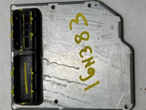
- Engine Control Module (ECM)
(OEM #12581144, 12590647, 12605330)— This is a potential cause if it is the module that has failed internally and is not communicating, but only after wiring and grounds have been confirmed to be good.
Trusted brands: ACDelco (OEM), Cardone
OEM price range: $400-$800
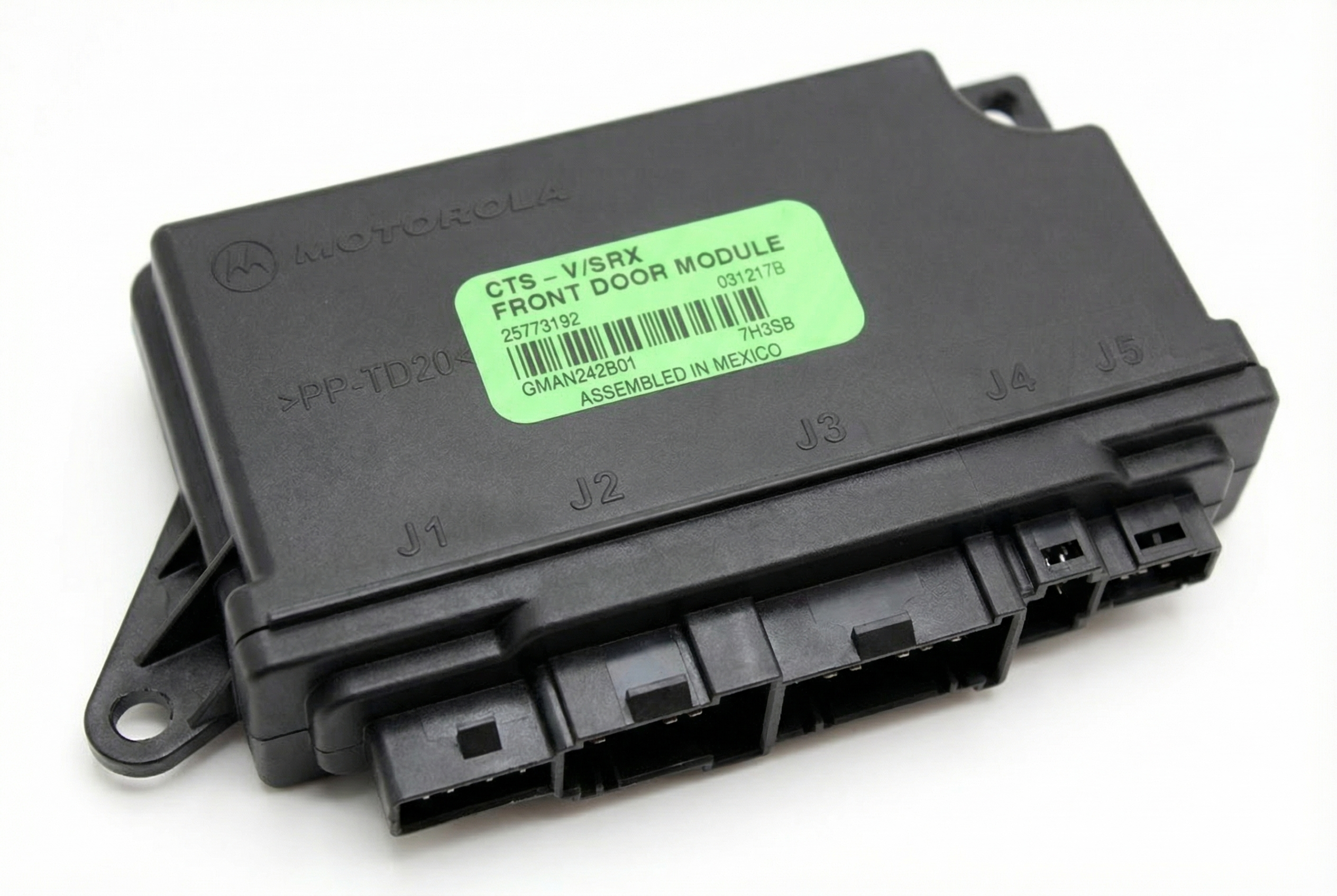
Aftermarket price range: $250-$500 - Body Control Module (BCM)
(OEM #15870719, 25720679)— The BCM acts as a gateway for many communication signals. Its failure can cause widespread network issues. It should only be replaced after being diagnosed as the specific point of failure.
Trusted brands: ACDelco (OEM), Dorman
OEM price range: $300-$600
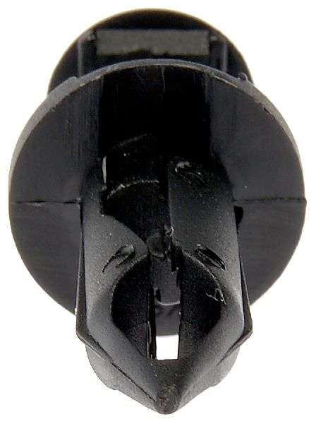
Aftermarket price range: $200-$400 - Wiring Repair Supplies — Often, the fix is not a replacement part but a repair to the existing harness using wire, butt connectors, and heat shrink tubing, especially given the known issue from TSB #PIC5460B.
OEM price range: $10-$30
Aftermarket price range: $5-$20
Related Codes That Often Appear With This One
- U0100 — A more generic code for Lost Communication With ECM/PCM. The TSB #PIC5460B explicitly lists this as a possible companion code when the ECM wiring is compromised.
- P1629, P0318, U1040, U1064, U1153, U1192, U1300 — These are various other communication and module-specific codes that TSB #PIC5460B notes can be stored in the ECM alongside a U1000 in other modules, all stemming from the same root wiring concern.
Technical Service Bulletins (TSBs) & Recalls
- PIC5460B: Addresses a no-crank or key-stuck-in-ignition concern, pointing to wiring issues on the Ignition 1 Power Feed (CKT 5290) or Class 2 data line (CKT 1807) to the ECM.
Platform-Specific Known Issues
- A known issue documented in GM Technical Service Bulletin #PIC5460B points to wiring concerns near the Engine Control Module. Specifically, the Ignition 1 Power Feed (circuit 5290) or the Class 2 data line (circuit 1807) can become damaged, causing code U1000 and a host of other communication DTCs.
- The physical location of the ECM, tucked behind the driver's side front wheel well liner, makes its connectors susceptible to water damage and corrosion if the liner is cracked, missing, or improperly installed.
- Technicians on professional forums report that a faulty Body Control Module (BCM) is a common point of failure that can bring down the entire Class 2 network, causing a flood of U1000 codes in other modules.
Mechanic-Grade Diagnostic Values
- Class 2 (J1850 VPW) Data Line Voltage — expected: A toggling square wave between 0V (inactive) and +7V (active/dominant). The bus is active at 7 volts nominal and inactive at ground potential.. Failure: A constant voltage above 7.5V (e.g., 10-12V) indicates a short to power from a faulty module. A constant voltage near 0V indicates a short to ground. A flat line with no activity indicates an open circuit or a module pulling the entire network down.
- Module Power Supply Voltage — expected: 12-15.5 volts during programming or key-on, engine-off diagnostics.. Failure: A reading below 12V, such as 8.1V measured at multiple modules, indicates a significant voltage drop from the power source, which can cause all modules to set U1000 codes despite being able to communicate with a scan tool.
Scan Tool Commands That Help
- GM Tech 2: Diagnostic Circuit Check > Class 2 Message Monitor — This function is critical for diagnosing a U1000 code. It performs a 'roll call' of all modules on the Class 2 network and shows their status as 'Active' or 'Inactive'. If a module is 'Inactive', it is the likely source of the communication breakdown. This test can be run even if the scan tool cannot communicate with individual modules in the normal way.
Wiring & Ground Locations

- G101 — Near the left front strut tower, grounds the Engine Control Module (ECM) and Transmission Control Module (TCM).. This is a primary ground for the main powertrain computers. A poor connection here can cause a no-communication scenario with the ECM, triggering U1000 in other modules.
- G103 — On the cowl in the left rear of the engine compartment, above the brake booster.. This ground serves the Body Control Module (BCM), Instrument Panel Cluster (IPC), Radio, and the Data Link Connector (DLC) itself. A fault here can disrupt communication across many interior systems and prevent a scan tool from connecting properly.
- G104 / G105 — G104 is on the right body rail near the headlamp; G105 is on the right side of the engine compartment (V6) or inner fender near the battery (V8).. These grounds serve various engine bay components, including the Underhood Fuse Block and EBCM (ABS module). A bad ground here can affect module power and communication.
- G201 — Behind the right kick panel.. This is an important interior ground point. A loose or corroded G201 can cause a host of intermittent electrical issues inside the cabin.
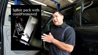
- Class 2 Splice Pack (Star Connector) — Often located behind the driver's or passenger's kick panel or under the dash. It's a black connector where multiple purple Class 2 data wires come together.. This is the central hub for the Class 2 network. A technician can remove a comb connector from the splice pack to isolate each branch of the network for testing, making it much easier to find which module or wire is causing the fault.
- ECM Connector C1, Pin 58 — At the Engine Control Module, located behind the driver-side front wheel well liner.. This is the specific pin for the Class 2 Serial Data line (Circuit 1807). It should be a Dark Purple wire. This is the primary test point for checking the data signal directly at the ECM.
Real Owner Repair Stories
- GMTNation forum user (Saab 9-7x (shared GM platform with similar electronics)) — Stalled while driving, then crank-no-start. Codes U1000, P0014, U1064, U1160.
❌ Tried (didn't work) Initial focus was on the camshaft position sensor (P0014) and checking wiring.
✅ What actually fixed it The root cause was a faulty ignition switch. The user was advised to check the output of the ignition switch before replacing other modules, as a failing switch can cause network communication codes and a no-start condition. - ADVANCED LEVEL AUTO YouTube Channel (2007 Cadillac CTS 3.6L) — Intermittent no-crank, key stuck in ignition, charging system not working, multiple U-codes for communication failure across all modules.
❌ Tried (didn't work) The owner had already replaced the battery and alternator with no success.
✅ What actually fixed it The diagnostic process involved using a scan tool to confirm widespread communication loss. The technician identified the Body Control Module (BCM) as the faulty component that was bringing down the entire Class 2 network. Replacing and programming the BCM resolved all symptoms. - Automotive Diagnostics & Programming YouTube Channel (2004 Cadillac CTS) — No-start condition with many U1000 codes.
❌ Tried (didn't work) The video warns against getting intimidated by the sheer number of codes and just picking one to diagnose.
✅ What actually fixed it The technician found that the ECM was not communicating. The final diagnosis pointed to a faulty ECM that was pulling down the network. The fix was to replace the ECM.
Model Year Variations Within This Range
- 2004-2005 vs 2006-2007 (CTS-V): For the high-performance CTS-V model, 2004-2005 models used the 5.7L LS6 V8 engine, while 2006-2007 models switched to the 6.0L LS2 V8. While the base communication architecture is the same, the ECM and engine-specific wiring are different. This is critical when ordering a replacement ECM, as they are not interchangeable between these year groups.
Helpful Videos

Used OEM Parts in Stock
New Aftermarket Parts Available


The information in this article is provided for general reference and educational purposes only. Vehicle specifications, procedures, and part compatibility can vary by production date, trim level, and region. Always consult your vehicle's factory service manual and verify part numbers before purchasing or performing repairs. Safety-critical components such as airbags, seat belts, and braking systems should be installed by a qualified professional.
- Cadillac CTS:
- 🧭 Diagnostic Flowchart
- 🎬 Helpful Videos
- 🛍️ Shop This Part
- What's Unique About the 2004-2007 Cadillac CTS
- Symptoms You May Notice
- Most Likely Causes
- Rare But Worth Checking
- Diagnosis Steps
- Parts You'll Likely Need
- Related Codes That Often Appear With This One
- Technical Service Bulletins (TSBs) & Recalls
- Platform-Specific Known Issues
- Mechanic-Grade Diagnostic Values
- Scan Tool Commands That Help
- Wiring & Ground Locations
- Real Owner Repair Stories
- Model Year Variations Within This Range
- 🎟️ Get 5% Off