
U1000 on 2004-2008 Cadillac SRX: Class 2 Communication Failure Causes and Fixes
U1000 on a 2004-2008 SRX means there's a communication breakdown on the Class 2 data network. This is often caused by a damaged wiring harness near the Engine Control Module (ECM), as cited in GM TSB #PIC5460B. Other common causes include poor battery/ground connections or a faulty Body Control Module (BCM). Expect to spend time on diagnosis, but the fix could be as cheap as a simple wire repair or cleaning a ground strap.
- U1000 is a network communication code, not a specific component failure code.
- For the 2004-2008 SRX, the most likely cause is a wiring issue near the Engine Control Module (ECM), as per TSB PIC5460B.
- Do not replace any modules until you have thoroughly checked all related power, ground, and data line wiring.
- Symptoms are often severe, including no-start and stalling, making the vehicle unsafe to drive.
- Diagnosing this code is complex and typically requires professional-level tools and expertise.
What's Unique About the 2004-2008 Cadillac SRX
The first-generation Cadillac SRX relies on the older Class 2 data communication network, which is a single-wire system that operates on a 0-7 volt fluctuating signal. 🎬 Watch: A deep dive into GM Class 2 data line repair. This makes it susceptible to network-wide failure if that single line is compromised by being shorted to ground or to a higher voltage. A specific GM Technical Service Bulletin (PIC5460B) directly links the U1000 code on this platform to wiring problems near the Engine Control Module (ECM), suggesting a known vulnerability in the harness routing or materials.
Diagnostic Flowchart
Tap your situation to follow the diagnostic path that matches what you're seeing on this vehicle.
Symptoms You May Notice
- Check Engine Light or other warning lights on the dashboard
- Vehicle will not start or cranks but won't run.
- Complete no-crank, no-start condition with no dash lights, as if the battery is dead.
- Engine stalling intermittently or while driving
- Unable to shift out of Park
- Key stuck in the ignition.
- Instrument cluster is dead or gauges behave erratically.
- Loss of features like power windows, HVAC, or radio.
- "Service Stabilitrak" or other messages on the Driver Information Center (DIC)
- Security light flashing or staying on solid
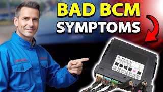
- Erratic behavior of lights, door locks, or wipers (often points to BCM issue) 🎬 See this guide on BCM symptoms and how to check them.
- Replacing the Engine Control Module (ECM) without first performing a thorough diagnosis of the wiring harness and power/ground circuits. The problem is very often in the wiring, not the module itself.
Most Likely Causes
- Damaged Wiring Harness to ECM 🔴 High Probability As documented in TSB #PIC5460B, the Ignition 1 Power Feed (circuit 5290) or the Class 2 data line (circuit 1807) to the ECM can become damaged, causing a loss of communication. Chafing, corrosion, or breaks in these wires where the harness routes near the engine are common.
How to confirm: Visually inspect the wiring harness leading to the Engine Control Module for any signs of chafing, rubbing against other components, or corrosion. Use a multimeter to check for proper voltage on the power feed wire and for continuity on the Class 2 data line (often a purple wire on GM vehicles of this era).
Typical fix: Repair the damaged section of the wire. This involves cutting out the compromised section, splicing in a new piece of wire with solder, and protecting the repair with heat-shrink tubing.
Est. part cost: $5-$20 - Poor Power or Ground Connections 🟡 Medium Probability Modules require stable voltage (typically 9-15V) to communicate. A weak battery, corroded battery terminals, or faulty main ground straps can cause intermittent voltage drops that disrupt the Class 2 network. GM vehicles of this era are known for having issues with ground straps. A forum user on MHH AUTO diagnosed a U1000 on a 2005 SRX by finding module voltage was only 8.1V, indicating a significant voltage drop.
How to confirm: Ensure the battery is fully charged and passes a load test. Clean the battery terminals and cable ends until they are bright metal. Locate and inspect the main engine and body ground straps for corrosion or looseness; wiring diagrams show key ground points like G103 on the cowl and G101 for the ECM. Perform a voltage drop test on the power and ground circuits to the non-communicating module; a drop of more than 0.1V indicates a problem.
Typical fix: Clean or replace corroded battery terminals or ground straps. Replace a weak battery.
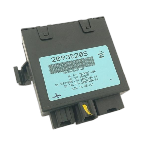
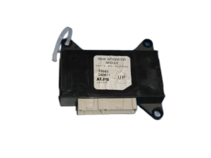
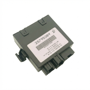
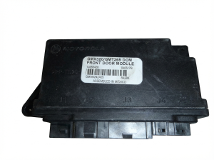
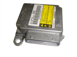
Est. part cost: $10-$250 - Faulty Body Control Module (BCM) 🟡 Medium Probability → Shop Body Control Module The BCM acts as a central hub for many body-related functions and is a key module on the Class 2 network. Its failure can disrupt the entire network, causing a U1000 code along with other seemingly unrelated electrical issues like erratic lights, wipers, and door locks. Water intrusion from a clogged sunroof drain or leaking cowl can also damage the BCM.
How to confirm: After confirming good power, grounds, and wiring to the BCM, observe its specific outputs. If multiple BCM-controlled systems (e.g., interior lights, power windows, security system) are malfunctioning simultaneously, the BCM is a strong suspect. A professional can isolate the BCM on the network to see if communication is restored to other modules.
Typical fix: Replace the Body Control Module. The new module must be programmed to the vehicle's VIN and options.
Est. part cost: $250-$700 - Faulty Control Module (ECM, ABS, etc.) ⚪ Low Probability Any module on the Class 2 network (ECM, BCM, TCM, ABS, etc.) can fail internally and either stop communicating or transmit corrupt data that brings down the entire network. A failing module can short the 7-volt data line to ground or to a higher voltage, silencing all other modules.
How to confirm: This is a process of elimination. After confirming all wiring, power, and grounds are good, the faulty module can be isolated by disconnecting modules one by one to see if communication is restored. This is often done at a central splice pack. When the faulty module is unplugged, the data line voltage should return to a normal 0-7V fluctuation.
Typical fix: Replace the faulty module. The new module will likely require programming to the vehicle's VIN.
Est. part cost: $200-$1000+
Rare But Worth Checking
- Aftermarket Electronics: Improperly installed aftermarket stereos, remote starters, or alarms can interfere with or damage the Class 2 data line, causing communication faults.
- Loose Fuse Block Connection: On some GM vehicles, a loose main fuse in the underhood fuse block can cause intermittent power loss to multiple modules, leading to a flood of U-codes.
- Faulty Powertrain/Main Relay: TSB #PIC5460B mentions that an intermittent main or powertrain relay can cause power loss to the ECM, resulting in communication codes. One owner of an SRX with a crank/no-start condition resolved the issue simply by swapping the fuel pump relay with another identical relay in the fuse box.
Diagnosis Steps
- Perform a full vehicle scan with a tool capable of communicating with all modules (e.g., a GM Tech 2). Note which modules are reporting a U1000 code and which, if any, are not communicating at all. A Tech 2's 'Class 2 Message Monitor' can show a list of all expected modules and their status (Active/Inactive).
- Check the battery voltage and ensure terminals are clean and tight. A weak or failing battery is a common cause of communication codes.
- Inspect all fuses in both the underhood and interior fuse boxes, especially those related to the ECM, BCM, and ignition.
- Following TSB #PIC5460B, perform a detailed visual inspection of the wiring harness connected to the Engine Control Module (ECM). Look for any signs of chafing, melting, or corrosion, particularly on the Ignition 1 Power Feed (circuit 5290) and the Class 2 data line (circuit 1807).
- If the harness appears intact, use a multimeter to verify battery voltage is present at the ECM's power input pin and check the integrity of the ground pins by performing a voltage drop test (less than 100mV is ideal).
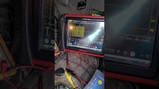
- Test the Class 2 data line (typically a purple wire on pin 2 of the OBD-II port) for activity using an oscilloscope. A healthy network will show a fluctuating square wave signal between 0 and 7 volts. 🎬 Watch: How to use an oscilloscope for Class 2 scope testing. A line that is stuck high (above 7V) or low (at 0V) indicates a short.
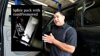
- If a short or open is suspected, locate the Class 2 splice packs (often located under the dash or in the driver's kick panel). By removing the comb that connects all the wires, you can isolate each module's data line individually to find which one is pulling the network down.
- If a specific module is suspected, disconnect its main electrical connector. If communication is restored to the rest of the network after unplugging it, that module is very likely faulty.
- If all wiring, power, and grounds are confirmed to be good, the module that is consistently failing to communicate is likely the source of the fault.
Parts You'll Likely Need
- Wiring Repair Supplies — If the cause is a broken or corroded wire as suggested by TSB #PIC5460B, you will need basic supplies to perform a proper repair.
- Body Control Module (BCM)
(OEM #10391431, 25720679 (2004-06), 22940857 (2007-09))— The BCM is a common failure point that can bring down the network. Part numbers vary by year, so a VIN check is required. - Battery — A weak battery can cause low voltage conditions that trigger communication codes across multiple modules.
Related Codes That Often Appear With This One
- U0100 — This is a more specific version of U1000, explicitly stating 'Lost Communication With ECM/PCM'. They often appear together when the ECM is the module that has dropped off the network.
- P0318, P1629, U1040, U1064, U1153, U1192, U1300 — TSB #PIC5460B lists these codes as being stored in the ECM alongside a U1000 in other modules, all stemming from the same wiring issue affecting the ECM's power or data line.
Technical Service Bulletins (TSBs) & Recalls
- PIC5460B: Addresses a no-crank or key-stuck-in-ignition concern where U1000 is stored. It points directly to a wiring concern (power feed or data line) to the Engine Control Module. It applies to both the SRX and the CTS.
Platform-Specific Known Issues
- TSB #PIC5460B specifically identifies the Ignition 1 Power Feed (circuit 5290) and the Class 2 data line (circuit 1807) to the ECM as potential failure points causing U1000 and a no-start condition.
- Owner experiences frequently point to checking battery terminal connections and main ground straps first, as corrosion is a common GM issue that can mimic complex module failures.
Mechanic-Grade Diagnostic Values
- Class 2 Data Line (CKT 1807) Voltage — expected: A fluctuating signal switching between approximately 0V (inactive) and 7V (active).. Failure: Voltage stuck high (>7V), stuck low (0V), or not returning fully to ground (e.g., resting at >100-200mV).
- Module Power Supply Voltage — expected: 9V - 15V with key on.. Failure: Voltage below 9V (e.g., 8.1V) indicates a significant voltage drop from the source.
- Voltage Drop on Power or Ground Circuit — expected: Less than 100mV (0.1V), with under 50mV (0.05V) being ideal.. Failure: A reading higher than 0.1V between the battery post and the module's power/ground pin indicates excessive resistance in the circuit.
- Ignition 1 Power Feed (CKT 5290) at ECM — expected: Should be equal to battery voltage with the ignition ON.. Failure: Any voltage significantly less than battery voltage points to a wiring or relay issue before the ECM.
Scan Tool Commands That Help
- GM Tech 2: Diagnostic Circuit Check -> Class 2 Message Monitor — This is the primary function for diagnosing a U1000 code. It polls all modules on the Class 2 network and provides a list showing each module's status as 'Active' or 'Inactive'. An 'Inactive' status immediately identifies the module that has stopped communicating, guiding the diagnostic effort.
Wiring & Ground Locations
- Class 2 Data Wire — Pin 2 of the Data Link Connector (DLC) under the driver's side dash. It is typically a purple wire (Circuit 1807).. This is the main data bus wire. All Class 2 communication happens on this single circuit, making it a critical point for testing the entire network's health with an oscilloscope.
- Splice Pack SP208 — Reported to be under the right side of the instrument panel.. A splice pack is a junction box where the Class 2 data wires from multiple modules meet. It allows a technician to easily isolate individual modules from the network to see which one might be shorting the data line.
- Ground G103 — On similar GM platforms, located on the cowl at the left rear of the engine compartment, above the brake booster.. This is a critical ground point that serves the BCM, Instrument Panel Cluster (IPC), and the Data Link Connector (DLC). A poor connection here can cause widespread communication failures.
- Ground G200 — Located behind the left kick panel.. This is another interior ground point. A loose or corroded ground here can cause intermittent issues with modules located inside the cabin.
- ECM Location — Left front side of the engine.. TSB #PIC5460B specifically points to wiring issues near the ECM, so knowing its location is key to inspecting the harness for chafing or damage as a first step.
Real Owner Repair Stories
- MHH AUTO forum (2005 Cadillac SRX) — U1000 stored in all Class 2 modules, no-start condition, unable to complete key learn procedure. All modules would communicate with a Tech 2 scanner, but showed low operating voltage of 8.1V.
❌ Tried (didn't work) Disconnecting various modules one-by-one did not resolve the low voltage or the U1000 codes.
✅ What actually fixed it The diagnostic path itself was the solution. The forum advised the user to stop focusing on individual modules and instead perform a systematic voltage drop test from the battery to the modules. The confirmed 8.1V reading at the modules, despite a healthy battery, proved the fault was in the power supply wiring or grounds, not a faulty module. - ScannerDanner Forum (2004 Cadillac SRX) — U1000 codes in 17 of 25 modules. One module (suspension control) was completely non-responsive. Oscilloscope testing showed the Class 2 data line voltage was not returning fully to ground, resting at 287mV.
❌ Tried (didn't work) Adding a temporary, direct ground wire., Disconnecting the non-communicating suspension control module did not restore normal network voltage.
✅ What actually fixed it The vehicle was not fixed; the customer declined further repairs after multiple shops, including a dealer, could not easily solve it. The key takeaway for a technician is that a resting voltage of ~300mV on the data line is abnormal and indicates a partial short or a faulty module that isn't fully pulling the line to ground. This case demonstrates a complex wiring fault that wasn't resolved by simply unplugging the most obvious culprit module.
OEM Part Supersession History
e.g., 10391431, 25720679→e.g., 22940857— Internal design updates or component changes by the manufacturer over the vehicle's production life.
Heads up: BCM part numbers for the first-generation SRX are year-specific. A BCM for a 2004-2006 model is generally not compatible with a 2007-2009 model, and vice-versa. Using the wrong part can result in a no-start condition or loss of features even after programming. Always verify the correct part number with the vehicle's VIN.
Model Year Variations Within This Range
- 2004-2006 vs. 2007-2009: The Body Control Module (BCM) part numbers are different between the earlier and later models of the first generation. While the diagnostic approach for a U1000 code is identical, the primary replacement part (if the BCM is at fault) is not interchangeable across these year ranges.
Helpful Videos

Used OEM Parts in Stock
New Aftermarket Parts Available


The information in this article is provided for general reference and educational purposes only. Vehicle specifications, procedures, and part compatibility can vary by production date, trim level, and region. Always consult your vehicle's factory service manual and verify part numbers before purchasing or performing repairs. Safety-critical components such as airbags, seat belts, and braking systems should be installed by a qualified professional.
- Cadillac SRX:
- 🧭 Diagnostic Flowchart
- 🎬 Helpful Videos
- 🛍️ Shop This Part
- What's Unique About the 2004-2008 Cadillac SRX
- Symptoms You May Notice
- Most Likely Causes
- Rare But Worth Checking
- Diagnosis Steps
- Parts You'll Likely Need
- Related Codes That Often Appear With This One
- Technical Service Bulletins (TSBs) & Recalls
- Platform-Specific Known Issues
- Mechanic-Grade Diagnostic Values
- Scan Tool Commands That Help
- Wiring & Ground Locations
- Real Owner Repair Stories
- OEM Part Supersession History
- Model Year Variations Within This Range
- 🎟️ Get 5% Off