
U1000 on 1999-2006 GMC Sierra 1500: Class 2 Communication Failure Causes and Fixes
Code U1000 on a GMT800 Sierra indicates a loss of communication between electronic modules. The most common causes are corroded ground wires (especially G201 under the driver's dash and G103 on the engine), a broken wire under the driver's side carpet or near the parking brake, or a failing Electronic Brake Control Module (EBCM). Finding the fix is a process of elimination, not a simple part replacement.
- U1000 on your Sierra means a communication network failure, not a single bad part.
- Before buying any parts, thoroughly inspect and clean the battery terminals and major ground points.
- The most likely culprit is a broken or corroded wire. Check under the driver's door sill plate and near the parking brake first.
- If wiring and grounds are good, the next step is to disconnect the Electronic Brake Control Module (EBCM) to see if it's the cause.
- Diagnosing this code requires patience and a methodical approach; it's a process of elimination.
What's Unique About the 1999-2006 GMC Sierra 1500
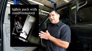
The 1999-2006 Sierra uses an older, single-wire communication protocol called Class 2 Serial Data (SAE J1850 VPW), not the modern two-wire CAN bus system. This single data wire (Pin 2 at the DLC, typically a dark green wire) and its related grounds are susceptible to interruption from a single point of failure. A short, open circuit, or even a corroded ground anywhere in the truck can bring down the entire network, leading to a cascade of seemingly unrelated symptoms. This makes diagnosing U1000 on these specific trucks a hunt for a wiring or module fault rather than a straightforward sensor issue. A central splice pack, SP205, located under the driver's side dash near the parking brake, is a key junction 🎬 Watch: GM Class 2 data line diagnosis and repair for the Class 2 network and a common area for diagnostic checks.
Symptoms You May Notice
- Check Engine Light is on
- ABS and Brake warning lights are on
- "Security" light is on or flashing
- Instrument cluster gauges are dead or behave erratically
- Vehicle will not start or has an intermittent no-start condition
- Service 4WD message or lights on the 4WD switch are out
- Power windows, door locks, or radio are inoperative
- Scan tool cannot communicate with one or more modules
- Message center displays errors like "Service Brake System"
- Replacing the ECM/PCM: The Engine Control Module is a robust component and rarely the cause of a U1000 code. The problem is almost always in the wiring to the module or another module on the network.
- Replacing the battery: While a weak battery can set a U1000 history code, it is not usually the root cause of a persistent, active communication failure with multiple symptoms.
Most Likely Causes
- Damaged or Corroded Wiring 🔴 High Probability The main data bus wire is often routed under the driver's side sill plate and carpet, where it is exposed to moisture and foot traffic. The harness near the emergency brake pedal is also a common chafe point. Rodent damage to harnesses, particularly near the underhood fuse box, has also been reported.
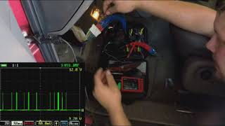
How to confirm: Visually inspect the wiring harness under the driver's door sill plate, under the carpet, and behind the emergency brake pedal assembly for breaks, corrosion (green crust), or chafing. A multimeter can be used to check for continuity on the Class 2 serial data wire (typically a dark green wire at the diagnostic port, pin 2). The voltage on this wire should fluctuate between 0 and 7 volts with the key on; a flatline voltage indicates a problem. 🎬 See how to diagnose GM Serial 2 with a multimeter
Typical fix: Repair the broken or corroded section of wire using solder and heat-shrink tubing. If a splice pack (like SP205) is corroded, it may need to be cleaned or replaced.
Est. part cost: $5-$25 - Bad or Corroded Grounds 🔴 High Probability Frame and body grounds are exposed to the elements, and critical engine grounds can be overlooked after service. A poor ground causes voltage fluctuations that disrupt the sensitive data signal. A forgotten ground strap after an engine or transmission swap is a very common cause.
How to confirm: Locate, remove, clean, and re-secure major ground points. Key locations include the ground block on the frame under the driver's door, the ground strap at the back of the passenger side cylinder head (G103), and grounds near the BCM (G201, inside on the driver's side A-pillar). G103 is a shared ground for the PCM and Generator-Battery Control Module and is a frequent culprit.
Typical fix: Clean the contact surfaces of the ground wire terminal and the chassis/engine block with a wire brush until shiny. Re-install securely.
Est. part cost: $0-$10 - Failing Electronic Brake Control Module (EBCM) 🟡 Medium Probability → Shop ABS Control Module The EBCM is located under the truck on the driver's side frame rail, where it is exposed to water, salt, and vibration. Internal failure, often of the power relay, can cause it to stop communicating or flood the data bus with noise.
How to confirm: With the key on, use a scan tool to see if you can communicate with the EBCM. If it's offline, disconnect the main electrical connector from the EBCM. If communication with other modules is restored, the EBCM is faulty. This is the most common module to fail and take down the network.
Typical fix: Replace the Electronic Brake Control Module. This part often requires programming or setup with a capable scan tool.
Est. part cost: $150-$400 - Faulty Aftermarket Electronics 🟡 Medium Probability Improperly installed aftermarket radios, remote starters, or alarms are often tapped into the wrong wires, interfering with the Class 2 data bus. The orange data wire in the radio harness is a common point of incorrect connection.
How to confirm: If an aftermarket device is installed, temporarily disconnect its power and data connections completely. Clear codes and see if normal communication resumes.
Typical fix: Remove the device or re-wire it correctly using a proper wiring interface/adapter that is compatible with the GM Class 2 system.
Est. part cost: $0-$75
Rare But Worth Checking
- Faulty Body Control Module (BCM): → Shop Body Control Module The BCM acts as a gateway for many communications. While not as common as EBCM failure, a bad BCM can take down the entire network. Diagnosis involves unplugging it to see if communication to other modules is restored.
- Faulty Instrument Panel Cluster (IPC): → Shop Instrument Cluster The IPC is an active module on the data bus. A failure in its internal circuitry can disrupt communication. This is less common but has been documented on forums.
- Faulty Ignition Switch: → Shop Ignition Switch A worn or faulty ignition switch can cause intermittent power loss to various modules, leading to communication dropouts and U1000 codes. One owner on GMTNation reported fixing their issue by replacing the ignition switch.
Diagnosis Steps
- Use a scan tool capable of reading GM-specific codes to check ALL modules for codes. Note which modules are communicating and which are not. A simple bluetooth scanner may not work.
- Check and charge the battery. Ensure battery terminals are clean and tight. Low voltage can cause communication errors.
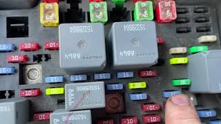
- Inspect all fuses in both the under-hood and interior fuse panels.
- Inspect and clean critical ground connections. The most important are the main frame ground under the driver's door, the engine ground G103 (back of passenger cylinder head), and the interior ground G201 (under dash near A-pillar).
- Disconnect the large electrical connector at the Electronic Brake Control Module (EBCM) on the frame rail. See if communication is restored to other modules. If so, the EBCM is faulty.
- Remove the driver's side door sill plate and peel back the carpet. Inspect the wiring harness for corrosion or damage. Pay close attention to any splice packs (often wrapped in black tape).
- Inspect the wiring harness near the emergency brake pedal for chafing or breaks.
- If aftermarket electronics (radio, remote start) are installed, disconnect them completely to isolate them as a cause.
- If the fault is still present, begin unplugging other modules on the Class 2 network one by one (BCM, IPC, etc.) using a process of elimination to see if 🎬 Watch: Helpful GM Class 2 network diagnosis tips one is bringing the network down. The splice pack SP205 is a useful central point for this.
Parts You'll Likely Need
- Electronic Brake Control Module (EBCM)
(OEM #19244893 (example for 2003-2004 models, verify by VIN))— This module is a very common failure point due to its exposed location, and a failure will bring down the communication network.
Trusted brands: ACDelco, Dorman
OEM price range: $300-$500
Aftermarket price range: $150-$400 - Wiring Repair Supplies — The most likely cause is a broken or corroded wire that needs to be repaired, not a part that needs to be replaced.
OEM price range: $5-$25
Aftermarket price range: $5-$25
Related Codes That Often Appear With This One
- U1016 — Loss of Communication with PCM
- U1041 — Loss of Communication with EBCM
- U1064 — Loss of Communication with BCM
- C0265 — EBCM Relay Circuit. Often indicates an internal EBCM failure that also causes the U1000.
Technical Service Bulletins (TSBs) & Recalls
- GM Preliminary Information Bulletin PIC3557: While for other models, it notes that U1000 diagnostics may not lead to a final repair and that the code can sometimes be set by the PCM looking for a signal from hardware that isn't present. It reinforces the need for a full network diagnostic approach rather than replacing the first module that flags the code.
Platform-Specific Known Issues
- Corrosion of the Class 2 data line splice under the driver's side door sill plate is a well-documented issue.
- The wiring harness can chafe against the emergency brake pedal mechanism, causing a short or open in the data line.
- Ground G103, located on the rear of the passenger-side cylinder head, is a common source of network problems if loose or corroded.
Mechanic-Grade Diagnostic Values
- Class 2 Data Line Voltage (DLC Pin 2 to Ground) — expected: Signal actively toggling between 0V and +7V (J1850 VPW square wave).. Failure: A steady voltage of 0V indicates a short to ground. A steady voltage significantly above 7V (e.g., 10-12V) indicates a short to power. A flat line at any other voltage indicates a bus problem.
- Class 2 Data Line Resistance to Ground — expected: There is no standard single resistance value for a healthy J1850 VPW bus as it is not terminated like a CAN bus. This measurement is less useful than a voltage test.. Failure: A reading of near-zero ohms would confirm a direct short to ground, but an open circuit or internal module fault will not be reliably found this way.
Hidden / Shadow Codes Worth Checking
- N/A (Module Status): This platform does not use 'shadow codes' for U1000. Instead, a professional scan tool (like the GM Tech 2) is used to poll the network and see a list of all modules. Each module will report as 'Active' or 'Inactive'. The module that is 'Inactive' is the one that has failed or lost connection, causing the U1000 code. (see via Using the 'Diagnostic Circuit Check' -> 'Class 2 Message Monitor' function on a GM Tech 2 or equivalent high-end scan tool.)
Scan Tool Commands That Help
- GM Tech 2: Class 2 Message Monitor — This is the primary diagnostic function for a U1000 code when you have no communication with any module. It allows the tool to listen for any activity and identify which modules are on the network and which are not, even if normal communication is impossible.
- GM Tech 2 / High-End Snap-on, Autel, etc.: Module Roll-Call / Automated System Scan — When communication is intermittent, this command attempts to connect to every possible module on the vehicle (PCM, BCM, EBCM, IPC, DDM, PDM, etc.). The resulting list of 'No Communication' modules points directly to the problem area.
Wiring & Ground Locations
- SP205 — Under the driver's side dash, typically taped to a harness near the emergency brake pedal assembly.. This is a splice pack where the Class 2 data wires from many different modules join together. Removing its shorting bar allows a technician to isolate each module's data wire and test it individually for shorts to power or ground, pinpointing the faulty circuit or module.
- EBCM Connector — On the Electronic Brake Control Module, mounted to the driver's side frame rail below the cab.. This connector is exposed to the elements and is a common point of failure. Disconnecting it is a primary diagnostic step; if communication is restored to the rest of the truck after unplugging it, the EBCM has failed internally and is taking the network down.
- BCM Connectors (C1-C6) — The Body Control Module is under the driver's side dash, above the pedals. It has multiple large connectors.. The Class 2 data line runs through the BCM. A fault in the BCM or its connectors can disrupt the entire network. The specific pin for the data line (often a Dark Green wire) can be tested here.
- DLC (Data Link Connector) Pin 2 — The OBD-II port under the driver's side dashboard.. Pin 2 is the Class 2 Serial Data line. This is the most accessible point to measure the data bus voltage to see if it's active (toggling 0-7V), shorted to ground (0V), or shorted to power (>7V).
Real Owner Repair Stories
- iATN (International Automotive Technicians Network) forum post (2006 Chevrolet Silverado 1500) — Dash inoperative, numerous warning lights, scan tool would not communicate with any module.
❌ Tried (didn't work) Initial scan with Snap-on Modis and Tech 2 failed to connect.
✅ What actually fixed it Rodents had chewed through the wiring harness near the underhood fuse box. The Class 2 data wire (Orange/Black in this case) was shorted to a power wire, causing a steady 11V on the data bus. Repairing the chewed wires restored all communication. - GMTNation forum user (2005 Chevrolet Trailblazer (similar GMT360 platform with Class 2)) — No start, no crank, multiple U1000 codes, gas gauge reads empty on full tank, no check engine light with key on.
❌ Tried (didn't work) Checking PCM/BCM powers and grounds., Cleaning PCM connectors after finding a mouse nest (no visible wire damage).
✅ What actually fixed it The ignition switch was faulty. The owner noticed that wiggling the key could sometimes make things work intermittently. Replacing the ignition switch resolved the no-start and communication issues. - YouTube video by 'Rico L' (GM Truck (GMT800 body style)) — No gauges, no power windows/locks, intermittent operation, no communication with scan tool when running.
❌ Tried (didn't work) Owner replaced the ignition switch, which did not fix the problem.
✅ What actually fixed it An internal fault in the Electronic Brake Control Module (EBCM) was causing it to send ~10V onto the 7V data line, shorting the network. Using the SP205 splice pack to isolate circuits, the technician identified the wire going to the EBCM as the source of the high voltage. Unplugging the EBCM restored communication to all other modules. Replacing the EBCM was the final fix.
"I Checked Everything" — The Actual Cause
- The diagnostic equivalent for a U1000 code is 'all wiring and grounds appear fine, but the fault persists.' In these cases, the cause is often an internal module failure or an intermittent component. A common example is a faulty Electronic Brake Control Module (EBCM) that shorts the data bus internally; the external wiring to it will test perfectly fine, but the module itself is flooding the network with incorrect voltage. Another documented cause is a failing ignition switch, which can intermittently cut power to modules, creating communication loss codes that are impossible to trace in the wiring itself.
Documented NHTSA Reports
- An owner reported in NHTSA ODI #10171770 that when their vehicle stalled, it lost ignition input; diagnostic codes including U1000 and U1016 were present, and the issue was resolved by replacing the ignition switch.
- According to NHTSA ODI #10186630, a vehicle experienced a no-crank/no-start condition and intermittent instrument panel cluster behavior with codes U1000 and U1016 set, while the shifter remained locked in park.
- In NHTSA ODI #10259771, an owner described the instrument panel cluster stopping work and a dealership identifying a U1000 Class 2 data link malfunction.
- NHTSA ODI #10169405 notes a report of a U1000 code related to an electrical and ground wire problem where the vehicle could not be driven.
- A report in NHTSA ODI #10970695 mentions a U1000 code and a CAN system diagnostic failure where the instrument cluster had no communication despite power and ground being present, requiring cluster replacement and further testing for BCM failure.
OEM Part Supersession History
88982323, 19144872→19244893 (ACDelco Remanufactured)— Standard part lifecycle replacement and consolidation.
Heads up: This part MUST be programmed with a GM-specific scan tool after installation to function correctly and communicate with the vehicle's other modules. Aftermarket alternatives like the Dorman 599-700 also exist but require programming.
Model Year Variations Within This Range
- 2003-2006: In 2003, GM implemented a 'Mid Cycle Enhancement' which significantly changed the vehicle's electrical architecture from the 1999-2002 models. While the Class 2 protocol remained, module locations, wiring colors, and BCM functions were updated. Diagnostics for a 2003+ model may not be identical to an earlier truck, so using the correct year-specific wiring diagram is critical.
- 2006 (Diesel): The 2006 LLY Duramax diesel engine received a new Engine Control Module (ECM) with different connectors (2-way instead of 3-way) compared to the 2004.5-2005 LLY. This is important to note if troubleshooting a diesel model, as the PCM pinouts will be different.
Diagnostic Flowchart
Other Known Issues on This Vehicle
Issues unrelated to this code that are worth knowing about as an owner of this generation:
- Instrument Cluster Stepper Motor Failure 🟠 Medium → Shop Instrument Cluster — Extremely common, especially on 2003-2006 models. Gauges will stick, read incorrectly, or stop moving entirely. (Ref: GM issued a special coverage adjustment for some vehicles, but it has since expired.)
- Intermediate Steering Shaft (ISS) Clunk 🟡 Low — Very common across all years. A clunking or popping noise is felt in the steering wheel, especially at low speeds. Caused by a lack of lubrication in the splined shaft. (Ref: GM released an updated part (PN 19153614) that is a greaseless design to fix the issue.)
- Rocker Panel and Cab Corner Rust 🔴 High — Almost guaranteed on vehicles used in the rust belt. The design traps moisture in the rocker panels and rear cab corners, leading to severe corrosion from the inside out.
- Rusted Brake Lines 🔴 High — Common on vehicles in corrosive environments. The factory steel brake lines lack sufficient coating and can rust to the point of failure, causing a sudden loss of braking.
- 4WD Transfer Case Encoder Motor/Sensor Failure 🟠 Medium → Shop Transfer Case Motor — A frequent issue where the 'Service 4WD' message appears and the system may not engage. Often caused by a faulty position sensor on the transfer case encoder motor.
- Fuel Level Sensor Failure 🟡 Low — Common problem where the fuel gauge becomes erratic or reads empty. Requires dropping the fuel tank to replace the sensor, which is part of the fuel pump module.
Used vs. New Parts: Buying Guide for This Vehicle
When a used part is the smart pick: For modules like the Body Control Module (BCM), Instrument Panel Cluster (IPC), or Radio, a used part from a junkyard can be a cost-effective option, BUT ONLY if you have access to a GM Tech 2 or equivalent scan tool to perform the necessary programming. For wiring harnesses or connectors, sourcing a used 'pigtail' with a few inches of wire can be much easier than re-pinning a damaged connector.
Donor-vehicle mileage cap: roughly under 150000 miles for the part to have meaningful remaining life.
What to inspect on the donor part:
- For modules, check for any signs of water intrusion or physical damage to the case or connectors.
- For wiring pigtails, ensure the connector pins are clean and straight, and that there is no corrosion or brittleness in the wires.
- Match part numbers EXACTLY. A module from a different year or with different options may not be compatible.
- Ask about the donor vehicle's history if possible (e.g., was it in a flood?).
Aftermarket brands forum-validated for this vehicle:
- For the EBCM, Dorman (e.g., 599-700) is a widely used and accepted aftermarket alternative to ACDelco.
- For wiring repairs, use quality primary wire (e.g., from Standard Motor Products) and adhesive-lined heat-shrink tubing.
Brands owners have reported issues with on this vehicle:
- Be cautious with no-name, ultra-cheap electronic modules from online marketplaces. They often have high failure rates or can cause other difficult-to-diagnose network issues.
Real Owner Stories
Aggregated from forums and TSBs cited above. Mileages and costs reflect what owners reported in those sources.
2006 GMC Sierra Denali
Symptoms: No IPC (Instrument Panel Cluster), No Start, U1000 Code following an engine swap.
What fixed it: Found a missing or loose ground at the G103 location on the rear of the passenger-side cylinder head.
Source hint: GMTNation - 'SOLVED! 2006 GMC Sierra Denali Engine Swap No IPC, No Start, U1000 Code'
2002 GMC Sierra 1500
Symptoms: Intermittent IPC Class 2 Serial Data Communication issues and DTC U1000.
What fixed it: Inspected the Class 2 data line splice under the driver's side door sill plate for corrosion.
Source hint: GM-Trucks.com - 'Intermittent Ipc Class 2 Serial Data Communication. Dtc U1000'
2004 GMC Sierra 1500
Symptoms: No Start, Multiple U1000 codes, Class 2 Serial Communication Problem.
What fixed it: Diagnostics focused on the splice pack SP205 as a central point to isolate which module was bringing down the network.
Source hint: GMTNation - 'No Start, Multiple U1000 codes, Class 2 Serial Communication Problem'
Related OBD-II Codes
Frequently Asked Questions
I just finished an engine swap on my 2006 GMC Sierra Denali and now I have a U1000 and a no-start condition. What should I check first?
My Sierra's ABS and Brake lights are on, and my scan tool can't talk to any modules. Could the EBCM be the problem?
Does GM Preliminary Information Bulletin PIC3557 mean I should just replace the PCM for a U1000 code?
I found green corrosion on a dark green wire under my driver's side door sill plate. Is this related to the U1000?
Can my aftermarket radio cause a U1000 code on a 1999-2006 Sierra?
Where are the most critical ground locations to check for a U1000 on this truck?
Helpful Videos
Used OEM Parts in Stock

New Aftermarket Parts Available

The information in this article is provided for general reference and educational purposes only. Vehicle specifications, procedures, and part compatibility can vary by production date, trim level, and region. Always consult your vehicle's factory service manual and verify part numbers before purchasing or performing repairs. Safety-critical components such as airbags, seat belts, and braking systems should be installed by a qualified professional.
- GMC Sierra 1500:
- 🧭 Diagnostic Flowchart
- 🎬 Helpful Videos
- 🛍️ Shop This Part
- What's Unique About the 1999-2006 GMC Sierra 1500
- Symptoms You May Notice
- Most Likely Causes
- Rare But Worth Checking
- Diagnosis Steps
- Parts You'll Likely Need
- Related Codes That Often Appear With This One
- Technical Service Bulletins (TSBs) & Recalls
- Platform-Specific Known Issues
- Mechanic-Grade Diagnostic Values
- Hidden / Shadow Codes Worth Checking
- Scan Tool Commands That Help
- Wiring & Ground Locations
- Real Owner Repair Stories
- "I Checked Everything" — The Actual Cause
- Documented NHTSA Reports
- OEM Part Supersession History
- Model Year Variations Within This Range
- Other Known Issues on This Vehicle
- Used vs. New Parts: Buying Guide for This Vehicle
- Real Owner Stories
- 2006 GMC Sierra Denali
- 2002 GMC Sierra 1500
- 2004 GMC Sierra 1500
- Related OBD-II Codes
- Frequently Asked Questions
- 🎟️ Get 5% Off