
U1000 on 2003-2008 Isuzu Ascender: Class 2 Communication Failure Causes and Fixes
On a 2003-2008 Isuzu Ascender, U1000 means a module has lost communication. The most likely causes are broken wires in the driver's door sill or liftgate harness, corroded grounds (especially G303 under the rear seat), or a faulty Body Control Module (BCM) under the rear seat, often due to moisture. Start by checking for broken wires in these common chafe points and cleaning grounds before replacing expensive modules.
- U1000 on this vehicle is a network communication code, not a specific part failure. Do not replace any computers until you have proven the wiring and grounds are good.
- The two most common places to find the problem are broken wires in the rear liftgate harness and the wiring harness under the driver's door sill.
- A weak battery or bad grounds can cause this code. Always check the simple electrical basics first.
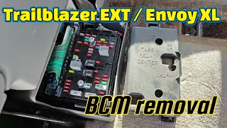
- If wiring and grounds are good, the next most likely culprit is the Body Control Module (BCM) under the rear driver's-side seat, which is susceptible to moisture damage.
- This is a difficult code for a DIYer to diagnose without experience in electrical troubleshooting. Professional help is recommended if the basic checks don't reveal the problem.
What's Unique About the 2003-2008 Isuzu Ascender
The Isuzu Ascender and its GM siblings (Chevy Trailblazer, GMC Envoy) use an older, single-wire communication protocol called Class 2 Serial Data (J1850 VPW). Unlike modern CAN bus systems, a single faulty module or a short in the one data wire can bring down the entire network, leading to a cascade of confusing symptoms. Owners and technicians frequently trace this code not to an expensive computer failure, but to physical wiring breaks in common chafe points like the driver's door sill harness, the flexible boot for the rear liftgate, or corrosion at key ground points and splice packs.
Symptoms You May Notice
- No crank / no start condition.
- Check Engine Light or other warning lights (ABS, Airbag, Security) are on or flashing.
- Instrument cluster gauges are dead, behave erratically, or sweep randomly at startup.
- Radio, climate controls (HVAC), and power windows/locks may not work.
- Message center displays 'UNKNOWN DRIVER' or other communication error warnings.
- Scan tool cannot communicate with one or more modules, or cannot read the VIN.
- Transmission may not shift correctly or may be stuck in one gear.
- Security light may be flashing, preventing the engine from starting.
- Vehicle may enter a "limp mode" or lose engine power unexpectedly, as noted in some manufacturer reports.
- Replacing the Engine Control Module (PCM) or Body Control Module (BCM) without first thoroughly inspecting all related wiring and ground connections. The fault is very often in the wiring, not the expensive computer.
Most Likely Causes
- Broken or Shorted Wiring in Harnesses 🔴 High Probability Wiring in the flexible rubber boot between the liftgate and the body, and the harness running under the driver's side door sill plate, are known to fatigue, break, or chafe over time. This can short the single Class 2 data wire (typically a dark green wire) to ground or power, bringing down the whole network.
How to confirm: Peel back the liftgate wiring boot and gently pull on each wire to check for breaks. 🎬 Watch: How to find and repair broken liftgate wires Remove the driver's side plastic door sill and inspect the wiring harness underneath for damage, especially near the parking brake mechanism and where the harness bends.
Typical fix: Repair the broken wire(s) using solder and heat shrink tubing. Ensure the repaired section is protected from future chafing with loom or high-quality tape.
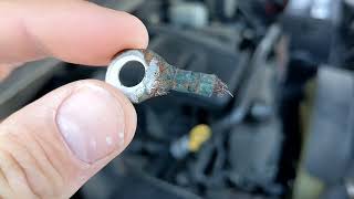
Est. part cost: $5-$20 - Corroded or Loose Ground Wires 🔴 High Probability Various essential ground points, particularly those for the Body Control Module (BCM) and Engine Control Module (PCM), can corrode, causing intermittent communication. Key locations include G303 under the rear seat and grounds on the engine block and cowl.
How to confirm: Locate the primary ground points. The BCM ground (G303) is often found under the driver's side rear seat area, on the lower right 'B' pillar. Engine and other body grounds (like G103 on the cowl above the brake booster) are also critical. 🎬 See how to fix a bad cowl ground connection Visually inspect for corrosion or looseness. Perform a voltage drop test with a multimeter to confirm a good ground.
Typical fix: Remove the ground bolt/nut, clean the wire terminal and the chassis/engine mounting point to bare metal with a wire brush, and re-secure it tightly. Apply dielectric grease to prevent future corrosion.
Est. part cost: $0-$10 - Faulty Body Control Module (BCM) 🟡 Medium Probability → Shop Body Control Module The BCM is located under the rear driver's-side seat, an area prone to moisture from spills, window leaks, or clogged sunroof drains. Corrosion on the BCM's large connectors is a common cause of network failure.
How to confirm: After ruling out wiring and grounds, access the BCM by lifting the rear seat cushion. 🎬 Watch: How to remove the BCM under the seat Disconnect the battery, then disconnect the BCM connectors and inspect the pins and sockets for any green or white corrosion or signs of water intrusion.
Typical fix: If corrosion is minor, it can sometimes be cleaned with an electrical contact cleaner and a small brush. If the module is internally damaged or heavily corroded, it must be replaced. A replacement BCM requires programming by a dealer or a specialized shop with a Tech 2 or equivalent scan tool.
Est. part cost: $150-$400 - Low Battery Voltage or Failing Alternator ⚪ Low Probability → Shop Alternator
How to confirm: Test the battery with a multimeter. A healthy, resting battery should be above 12.4V. With the engine running, voltage should be between 13.5V and 14.5V. A load test is the most definitive way to confirm battery health. Low voltage during startup can cause modules to fail their initial communication check.
Typical fix: Charge or replace the battery. If the alternator is not charging correctly, it will need to be replaced.
Est. part cost: $150-$450
Rare But Worth Checking
- Faulty OnStar Module (VCIM): The OnStar module (Vehicle Communication Interface Module) is known to fail and can disrupt the Class 2 network. Since the analog service is obsolete, a common diagnostic step and permanent fix is to simply unplug the module. It is typically located under the rear passenger-side seat.
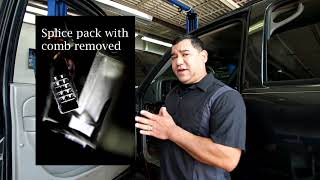
- Corroded Splice Pack: The Class 2 data wires from many modules meet at a junction block called a splice pack (e.g., SP205). SP205 is located under the driver's side dash, often taped to the main harness near the headlight switch connector. Corrosion or a bad connection inside this pack can cause a network-wide failure. Diagnosis involves removing the shorting comb and testing circuits individually, which is an advanced procedure.
- Faulty Aftermarket Radio/Electronics: An improperly installed aftermarket radio or other electronic device can interfere with or short out the Class 2 data line, as the radio is an integral part of the network for chimes and other functions. If you have an aftermarket head unit, it's a primary suspect.
Diagnosis Steps
- Check Battery Health: Ensure the battery has a full charge (12.4V+ resting) and that the alternator is charging correctly (13.5-14.5V running). A weak battery is a simple but common cause.
- Scan for All Codes: Use a high-quality scan tool that can communicate with all modules (BCM, ABS, Airbag, etc.). Note which modules are reporting 'Lost Communication' and which are not responding at all.
- Inspect Fuses: Check all fuses related to the BCM, PCM, and other non-communicating modules in both the under-hood and interior fuse panels. Pay special attention to fuses labeled 'TBC' (Truck Body Controller).
- Inspect Common Wiring Failure Points: Visually and physically inspect the wiring harness inside the rubber boot of the rear liftgate and under the driver's door sill trim for any broken, chafed, or pinched wires. The Class 2 data wire is typically dark green.
- Inspect and Clean Grounds: Locate, remove, and clean the main engine-to-chassis and battery-to-chassis ground straps. Crucially, inspect and clean ground G303 under the rear driver's side seat and G103 on the cowl behind the brake booster.
- Inspect BCM Connectors: Lift the rear driver's side seat to access the BCM. Disconnect its connectors and check for any signs of corrosion or moisture damage.
- Check Class 2 Data Line Voltage: With the key on, engine off, use a multimeter to check the voltage on Pin 2 of the OBD-II port. A healthy Class 2 network should show fluctuating voltage, toggling between 0V and 7V. A line stuck at a constant voltage (e.g., 5V, 10V, or 12V) indicates a short to power from a faulty module.
- Isolate Modules (Advanced): If a short is detected, the next step is to isolate modules one by one to find which one is pulling the network down. This is typically done at splice pack SP205 by removing the comb and testing the data line voltage as you reconnect each circuit one by one. This is a task best left to a professional.
Parts You'll Likely Need
- Body Control Module (BCM)
(OEM #ACDelco #15116070 or #15135997 (Part numbers vary by year and options, always verify with VIN))— The BCM is a central hub for the Class 2 network and is prone to failure from moisture and internal shorts.
Related Codes That Often Appear With This One
- U1016 — Lost Communication with PCM. This often appears with U1000 when the PCM is the module that has dropped off the network, frequently leading to a no-start condition.
- U1041 — Lost Communication with EBCM (ABS Module). This indicates the brake control module is not communicating, which will disable ABS and traction control.
- U1064 — Lost Communication with BCM. This code specifically points to a communication loss with the Body Control Module.
- U0073 — Control Module Communications Bus OFF. This is a more general code indicating the entire communication bus is down, often seen alongside U1000.
Technical Service Bulletins (TSBs) & Recalls
- While no specific TSB number for U1000 on the Ascender was located, numerous GM TSBs exist for the broader GMT360 platform regarding Class 2 communication loss (U1000, U0073). These bulletins often point towards checking for backed-out terminals in connectors, inspecting splice packs, and verifying ground integrity before module replacement.
- Manufacturer service bulletin TSB NTB06-009 (referenced in NHTSA ODI #10150585) describes a CAN communication circuit malfunction that can lead to a vehicle entering "limp mode" and setting code U1000.
Mechanic-Grade Diagnostic Values
- Class 2 Data Line Voltage (Oscilloscope) — expected: A toggling square wave between 0 volts and 7 volts.. Failure: A flat line at any voltage, or a line stuck high (e.g., 10V or 12V), indicates a short to power or ground from a faulty module or wire.
- Class 2 Data Line Voltage (Multimeter) — expected: A fluctuating voltage that is not a stable reading. While not as accurate as a scope, it should not be a fixed number.. Failure: A steady, non-fluctuating voltage reading (e.g., 0V, 5V, 12V) suggests a shorted data line.
- Resistance of individual Class 2 circuits to ground — expected: Each module's data line circuit should have a similar resistance reading to ground when disconnected from the splice pack. There is no universal spec, but they should be consistent with each other.. Failure: One circuit reading significantly different from the others (e.g., close to 0 ohms) points to the module or wiring on that circuit as the source of a short to ground.
Scan Tool Commands That Help
- GM Tech 2: View 'Module Status' or 'Class 2 Message Monitor' — This function allows a technician to see a list of all modules on the network and which ones are actively communicating. It's the fastest way to see which module has dropped off the network and is likely causing the U1000 code.
- GM Tech 2: Isolating modules at Splice Pack (SP205) — This is a manual diagnostic procedure, not a direct command. With the Tech 2 connected, the technician removes the shorting bar from SP205 and reconnects one circuit at a time. When the faulty circuit is reconnected, communication on the Tech 2 will be lost, identifying the problematic branch of the network.
Wiring & Ground Locations
- SP205 — Splice pack located behind the driver's side of the dashboard, often taped to the main harness near the headlight switch connector.. This is the central junction for many Class 2 data lines. Corrosion inside or a bad connection can take down the entire network. It's the primary access point for isolating individual module circuits during diagnosis.
- SP306 — Splice pack located in the body harness, under the right rear seat.. This splice pack connects rear-body modules to the main network via SP205. A short in the wire between SP205 and SP306 can cause a network failure that appears to be related to a rear module.
- G303 — On the lower right 'B' pillar, typically accessed by removing the rear seat cushion on the driver's side.. This is a critical ground point for the Body Control Module (BCM) and other nearby components. Corrosion here is a very common cause of BCM communication failure.
- G103 — Located at the left rear of the engine compartment on the cowl, above the brake booster.. This ground serves multiple modules, including the Instrument Panel Cluster (IPC), BCM, and the Data Link Connector (DLC) itself. A bad ground here can cause widespread communication issues.
- BCM Connector C1 (Pin B1) — The C1 connector at the BCM (under the left rear seat) is typically Gray. Pin B1 is the Class 2 Serial Data wire (Dark Green/White or Light Green).. This is the direct data line connection to the BCM. Checking for voltage/signal here can confirm if the BCM itself is receiving data or if it's the source of the problem.
Real Owner Repair Stories
- GMTNation Forum User (2005 Trailblazer 4.2L) — No crank, no start, no radio, no power windows/locks.
❌ Tried (didn't work) Initial checks of fuses and grounds were inconclusive.
✅ What actually fixed it Using an oscilloscope, the owner isolated circuits at splice pack SP205. Pin H, which runs to splice pack SP306 under the rear seat, was causing the entire network to go down. The wire between SP205 and SP306 was shorted. Running a new bypass wire between the two splice packs resolved the issue. - YouTube video by 'x298racer' (2002 Trailblazer) — U1000 code present, no lights on the 4-wheel drive selector switch, scan tool could not communicate.
❌ Tried (didn't work) Replacing the 4WD selector switch, checking fuses.
✅ What actually fixed it The Transfer Case Control Module (TCCM), located under the driver's side dash, had failed internally and was shorting out the Class 2 data line. Replacing the TCCM restored communication and fixed the 4WD system. - CorvetteForum User 'SpeedyZ' (GM Vehicle with Class 2 Bus (Corvette, but principle applies)) — Multiple communication codes, loss of communication with modules.
❌ Tried (didn't work) Standard checks did not immediately find the cause.
✅ What actually fixed it The Instrument Panel Cluster (IPC) itself had an internal short, grounding the Class 2 data bus at approximately 10 ohms. Unplugging the IPC from the network restored communication among all other modules. The IPC was the faulty component. - Chevrolet Forum User (2002 Trailblazer LT) — Rear wiper not working, which can be tied to the Liftgate Control Module (LGM) on the data bus.
❌ Tried (didn't work) Testing power at the motor connector showed 12V, but the motor wouldn't run.
✅ What actually fixed it The problem was traced to the Liftgate Control Module (LGM), which receives a signal over the Class 2 data line (dark green wire). A fault in the LGM or its connection to the data bus can cause U1000 and other strange electrical issues related to the rear hatch. In many cases, broken wires in the hatch boot are the cause, but a faulty LGM itself can also be the culprit. - NHTSA ODI #10171770 (GM Platform) — An owner reported that when the vehicle stalled, it lost ignition input. Codes found during the scan check included U1000, U1016, U1152, B1372, and U1088. The issue was resolved by replacing the ignition switch.
- NHTSA ODI #10259771 (GM Platform) — A report describes an instrument panel cluster that stopped working. A dealership scan revealed code U1000 (Class 2 Data Link Malfunction), though the cluster was intermittently operable at the time of the inspection.
- NHTSA ODI #10970695 (Cross-Manufacturer) — A technician noted that after finding no communication with the instrument cluster despite power and ground being present, the BCM was tested for failure following the installation of a replacement cluster.
- NHTSA ODI #11244385 (GM Platform) — An owner reported the vehicle losing engine power and the Stabilitrak light illuminating while throwing codes P0700, U0073, and U1000. The vehicle would buck and the odometer, RPM gauge, and temperature gauge would malfunction.
OEM Part Supersession History
Varies by year/options (e.g., 15116070, 15135997)→Varies, check with GM dealer using VIN— Revisions to fix hardware flaws or accommodate software updates.
Heads up: A BCM must be programmed with the vehicle's VIN and specific RPO codes (options). A used BCM from a donor vehicle with different options (e.g., sunroof, 4WD, premium sound) will cause features to work incorrectly or not at all, and may set additional communication codes. While a used BCM can be reprogrammed by a dealer or specialist, it is not a plug-and-play part.
Model Year Variations Within This Range
- 2002-2009: The number of modules on the Class 2 data bus increased in later model years. While the fundamental diagnostic process is the same, later years have more potential modules (like digital radio receivers, advanced HVAC controls) that could be the source of a network short.
Diagnostic Flowchart
Other Known Issues on This Vehicle
Issues unrelated to this code that are worth knowing about as an owner of this generation:
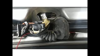
- Failing Fan Clutch 🔴 High — Very common, especially after 80,000 miles. Symptoms include a loud 'jet engine' or roaring noise from the engine bay, overheating at idle, and reduced power/fuel economy.
- Instrument Cluster Gauge Stepper Motor Failure 🟠 Medium → Shop Instrument Cluster — Extremely common across all GMT360s. Gauges (speedometer, tachometer, etc.) become stuck, read incorrectly, or stop working entirely. The fix is to replace the small stepper motors on the cluster's circuit board. (Ref: GM offered a special coverage adjustment for some vehicles, but it has long since expired.)
- Cracked Exhaust Manifold 🟠 Medium — Common on the 4.2L I6 engine. Results in a ticking noise, especially when cold, that may quiet down as the engine warms up. Can cause an exhaust leak and trigger lean codes.
- Failed 4WD Actuator / Encoder Motor 🟠 Medium — Common on 4x4 models. The transfer case actuator fails, leading to a 'Service 4WD' light and inability to switch between 2WD, A4WD, 4HI, and 4LO modes.
- Rear Air Suspension Failure 🔴 High — Very common on models equipped with the optional air suspension (Envoy, Rainier, Ascender). Air springs develop leaks or the compressor fails, causing the rear of the vehicle to sag. Many owners convert to conventional coil springs.
- Fuel Level Sensor Failure 🟡 Low — Common issue where the fuel gauge becomes erratic or reads empty. The sensor is part of the fuel pump module inside the tank. (Ref: GM had a special policy for some models to co-pay for the repair, but it is likely expired.)
Used vs. New Parts: Buying Guide for This Vehicle
When a used part is the smart pick: A used Body Control Module (BCM) from a reputable salvage yard is a viable option, but ONLY if you have access to a GM Tech 2 scanner or a service that can reprogram it to your vehicle's VIN and options. Used wiring harnesses or connectors are also good for repairing damaged sections.
Donor-vehicle mileage cap: roughly under 150000 miles for the part to have meaningful remaining life.
What to inspect on the donor part:
- For a BCM, ensure the donor vehicle was not a flood vehicle. Inspect the module's connectors for any signs of green or white corrosion before purchase.
- For wiring harnesses, look for sections that are uncut, have not been previously repaired (look for non-factory tape or splices), and are not brittle or cracked.
OEM-only on this vehicle (don't cheap out):
- Body Control Module (BCM): While used OEM is an option, it's strongly recommended to use a genuine ACDelco part (new or remanufactured) or a properly programmed used unit. Avoid generic, unbranded aftermarket BCMs as they often have programming and compatibility issues.
Aftermarket brands forum-validated for this vehicle:
- Dorman offers remanufactured BCMs (e.g., part #502-006) that are a common alternative to dealer parts, but they still require professional programming.
Brands owners have reported issues with on this vehicle:
- Unbranded, no-name BCMs from online marketplaces should be avoided. They often fail to program correctly or have a high premature failure rate.
Real Owner Stories
Aggregated from forums and TSBs cited above. Mileages and costs reflect what owners reported in those sources.
2002 GMC Envoy (GMT360 Platform Mate)
Symptoms: The vehicle experienced a no-start, no-crank condition with no communication to the modules.
What fixed it: The issue was traced to the Class 2 serial communication line and required diagnosing the splice pack locations to find the communication break.
Source hint: GMTNation.com thread titled 'Need help U1000 code Class 2 serial communication problem'
2002-2009 Chevrolet TrailBlazer (GMT360 Platform Mate)
Symptoms: U1000 and other codes present, resulting in a no-start, no-crank, and no-communication state.
What fixed it: The problem was identified as a Class 2 data link malfunction where one or more modules were not talking or listening properly.
Source hint: Trailvoy.com thread titled 'U1000 and other codes no start no crank no communication'
Related OBD-II Codes
Frequently Asked Questions
Why is my 2003-2008 Isuzu Ascender displaying 'UNKNOWN DRIVER' on the message center?
Where is the BCM located on my Ascender, and why does it cause U1000?
I found broken wires in the rubber boot of my liftgate; could this cause a no-start condition?
Is there a specific ground point I should check for U1000 on my Ascender?
Can I just swap in a used BCM to fix the U1000 code?
What should the voltage be on my OBD-II port if the network is healthy?
Helpful Videos
Used OEM Parts in Stock
New Aftermarket Parts Available


The information in this article is provided for general reference and educational purposes only. Vehicle specifications, procedures, and part compatibility can vary by production date, trim level, and region. Always consult your vehicle's factory service manual and verify part numbers before purchasing or performing repairs. Safety-critical components such as airbags, seat belts, and braking systems should be installed by a qualified professional.
- Isuzu Ascender:
- 🧭 Diagnostic Flowchart
- 🎬 Helpful Videos
- 🛍️ Shop This Part
- What's Unique About the 2003-2008 Isuzu Ascender
- Symptoms You May Notice
- Most Likely Causes
- Rare But Worth Checking
- Diagnosis Steps
- Parts You'll Likely Need
- Related Codes That Often Appear With This One
- Technical Service Bulletins (TSBs) & Recalls
- Mechanic-Grade Diagnostic Values
- Scan Tool Commands That Help
- Wiring & Ground Locations
- Real Owner Repair Stories
- OEM Part Supersession History
- Model Year Variations Within This Range
- Other Known Issues on This Vehicle
- Used vs. New Parts: Buying Guide for This Vehicle
- Real Owner Stories
- 2002 GMC Envoy (GMT360 Platform Mate)
- 2002-2009 Chevrolet TrailBlazer (GMT360 Platform Mate)
- Related OBD-II Codes
- Frequently Asked Questions
- 🎟️ Get 5% Off