
U1002 on 2011-2014 Nissan Quest: Causes and Fixes for CAN Communication Loss
U1002 on a 2011-2014 Nissan Quest indicates a CAN network communication failure. The most common causes are a weak battery, corroded ground wires, or damaged wiring, not an expensive module failure. Always check the battery and clean the main ground connections, particularly the strap from the transmission to the chassis, before attempting complex repairs.
- U1002 is a network problem, not a component problem. Do not replace expensive computers unless they are proven to be faulty through professional diagnosis.
- The most likely cause is simple and cheap to fix: a weak battery or a corroded ground wire. Always start your diagnosis there.
- A visual inspection is powerful. Look for green/white corrosion on battery terminals, frayed ground straps, and damaged wiring harnesses.
- This code can cause a wide range of strange, seemingly unrelated electrical symptoms. The root cause is almost always a foundational electrical issue.
- Due to the complexity of CAN networks, if basic checks of the battery and grounds don't solve the problem, professional diagnosis is strongly recommended.
What's Unique About the 2011-2014 Nissan QUEST
The 2011-2014 Nissan Quest (RE52 generation) shares its electrical architecture with many other Nissans from this era, which are known to be sensitive to voltage and ground issues. Unlike some vehicles where a specific module is a known weak point, this code on a Quest is more frequently a result of systemic issues in the vehicle's electrical foundation. Problems like corroded ground straps, particularly the one connecting the transmission case to the chassis, and failing batteries are common culprits that can cause widespread, confusing communication faults across the network.
Diagnostic Flowchart
Tap your situation to follow the diagnostic path that matches what you're seeing on this vehicle.
Symptoms You May Notice
- Check Engine Light is on
- Multiple warning lights on the dashboard (ABS, VDC, SLIP, etc.) may illuminate simultaneously
- Erratic or non-functional gauges (speedometer, tachometer)
- Harsh or erratic transmission shifting
- Vehicle may crank but fail to start
- Intermittent stalling
- Power windows, radio, or other electronic accessories may not work correctly
- Cooling fans running at high speed when they shouldn't be
- Replacing the control module that stored the U1002 code. The TSBs clearly state that the module reporting the code is often working normally and is simply indicating a network problem it has detected.
- Replacing the Transmission Control Module (TCM) or Engine Control Module (ECM) without first verifying all power and ground connections are perfect.
Most Likely Causes
- Low Battery Voltage or Poor Battery Connections 🔴 High Probability → Shop Vehicle Battery Modern vehicles are highly sensitive to voltage, and a battery below 12.4V (or below 10V while cranking) can cause modules to stop communicating randomly. Corrosion on terminals is a frequent source of these issues.
How to confirm: Test the battery with a multimeter; it should read above 12.4V with the engine off. Perform a load test to check its true health. Inspect terminals for any white or green corrosion and ensure they are tight.
Typical fix: Clean the battery terminals and cable ends with a wire brush and a baking soda solution. If the battery fails a load test, it must be replaced.
Est. part cost: $120-$250 - Corroded or Loose Ground Wires 🔴 High Probability Ground straps from the engine and transmission to the chassis are exposed to the elements and frequently corrode, creating high resistance that disrupts module communication. This is a very common failure point on Nissans of this era, with the transmission-to-chassis ground being a primary suspect.
How to confirm: Visually inspect the main ground connections: from the negative battery terminal to the chassis, and the braided strap from the transmission housing to the chassis/frame rail. Look for green/white corrosion, fraying, or looseness. A voltage drop test across the ground connection while the engine is running can confirm high resistance (should be <0.2V).
Typical fix: Remove, clean all contact points to bare metal, and securely re-tighten the ground connections. If the strap is badly corroded or broken, it must be replaced.
Est. part cost: $15-$50 - Damaged or Corroded Wiring Harness/Connectors 🟡 Medium Probability Connectors for modules located in the engine bay or under the vehicle are susceptible to moisture intrusion and corrosion. Wires can also chafe against the chassis or engine components over time, especially in the bundle near the IPDM.
How to confirm: Visually inspect the wiring harnesses connected to the ECM, TCM, and ABS module for any signs of physical damage, chafing, or green/white corrosion on the pins. A 'wiggle test' on harnesses, particularly near the IPDM, while the vehicle is on may trigger or resolve the fault.
Typical fix: Clean corroded pins carefully with an electrical contact cleaner. Repair damaged wires using solder and heat shrink tubing. Replace the connector if it is too damaged to be salvaged.
Est. part cost: $5-$100 - Faulty Intelligent Power Distribution Module (IPDM) ⚪ Low Probability → Shop Fuse Box The IPDM, which is the 'smart' fuse and relay box in the engine bay, is a known failure point on many Nissan models. Internal relay failures (like the non-serviceable ECM relay) can cut power to other modules, causing CAN communication codes and no-start conditions.
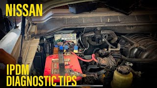
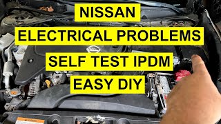
How to confirm: A technician can perform a self-test on the IPDM by turning the ignition on and pressing the driver's door switch 10 times in 20 seconds; this will cycle various components like lights and wipers. If the IPDM fails to respond or doesn't power certain circuits, it is suspect. Swapping the ECM relay with an identical one (like for the fog lamps) can be a quick diagnostic step if applicable.
Typical fix: Replacement of the IPDM unit. This is typically a plug-and-play part with no programming required.
Est. part cost: $200-$500
Rare But Worth Checking
- Faulty Control Module (ECM, TCM, ABS): While possible, a control module is rarely the cause. The module reporting the code is usually working correctly. This should only be considered after all wiring, power, and ground issues have been definitively ruled out by a professional.
- Aftermarket Accessories: Improperly installed remote starters, alarms, or stereo equipment tapped into the CAN bus can disrupt communication and cause U-codes. These should be disconnected as a primary diagnostic step.
Diagnosis Steps
- Check Battery Health: Ensure the battery voltage is above 12.4V with the engine off and that it passes a load test. Clean any corrosion from the terminals. A weak battery is a primary cause of U-codes.
- Scan All Modules: Use an advanced scan tool to read codes from ALL modules (ECM, TCM, BCM, ABS, etc.). Note which modules are communicating and which are not. This helps pinpoint the area of the fault.
- Inspect Main Grounds: Locate, disconnect, clean to bare metal, and retighten the primary ground connections. Focus on the negative battery cable-to-chassis ground and the engine/transmission-to-chassis ground strap. This is the most common fix.
- Inspect Fuses: Check all fuses related to the main control modules in both the engine bay (IPDM) and interior fuse panels. High-level fuses like 'Ignition 1' and 'Elec B' power multiple modules.
- Visual Wiring Inspection: Carefully inspect the main wiring harnesses for chafing, corrosion, or damage, especially around the battery tray, engine, and transmission. Pay attention to the harness bundle near the IPDM.
- Check CAN Bus Resistance: Disconnect the negative battery terminal. At the OBD-II port, measure the resistance between Pin 6 (CAN High) and Pin 14 (CAN Low). A healthy network should read approximately 60 ohms. A reading of 120 ohms indicates 🎬 See this walkthrough on diagnosing Nissan CAN communication line faults. an open circuit or a faulty terminating module/resistor. An open or shorted reading points to a wiring harness issue.
- Isolate Modules (Advanced): If resistance is incorrect (e.g., 120 ohms), a technician may begin unplugging modules one by one to find which one is causing the network issue. The two terminating modules (often the ECM and IPDM) should each have 120 ohms of resistance internally. This requires a wiring diagram and professional expertise.
Parts You'll Likely Need
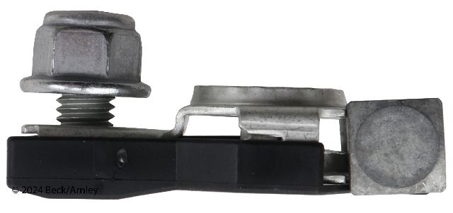
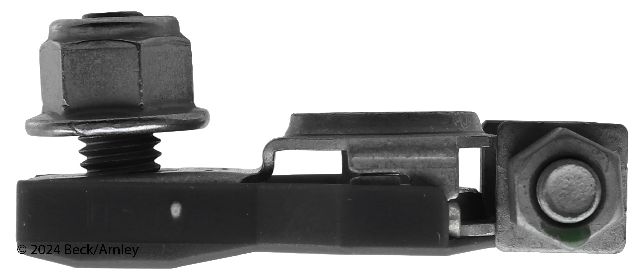
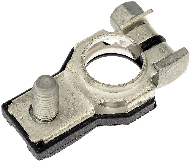
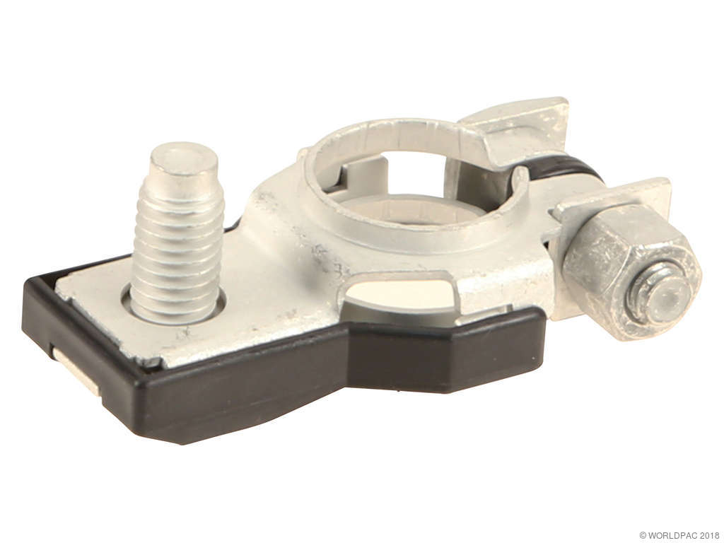
- Battery Ground Cable/Strap
(OEM #24080-1JA0A)— The main ground straps are highly prone to corrosion and are a primary cause of this code. Cleaning is often sufficient, but replacement is needed if the cable is frayed or broken.
Trusted brands: Nissan OE, Standard Motor Products, Dorman
OEM price range: $40-$80
Aftermarket price range: $15-$40 - Battery — A weak or failing battery is a very common trigger for communication codes on modern vehicles.
Related Codes That Often Appear With This One
- U1000 — U1000 is a general CAN communication failure code. U1002 is a more specific version with a tighter timing requirement, and they often appear together as they indicate the same type of network fault.
- U1001 — This code specifically points to a loss of communication with the ECM and can appear with other U-codes during a network-wide issue caused by bad power or grounds.
- U1010 — This code indicates a module has an internal error. If one module fails internally, it can bring down the network, causing other modules to log U1002.
Technical Service Bulletins (TSBs) & Recalls
- NTB10-066A / NTB10-066B: CAN Communication Codes – Diagnostic Tips & Guidelines. Explains that U1002 has a tighter timing spec than U1000 and that the module reporting the code is usually not the faulty part.
- NTB13-027C: CAN Communication - Network Diagnostic Flow Chart. Provides a detailed diagnostic procedure, emphasizing checking power and grounds first.
- NTB10-145B: ABS/VDC CAN Diagnosis Information. Provides a flowchart for diagnosing CAN issues when the ABS/VDC system is involved.
Platform-Specific Known Issues
- Transmission to Chassis Ground Strap Corrosion: → Shop Engine Ground Strap Like its platform mates (Rogue, Murano), the Quest is prone to corrosion on the main ground strap connecting the transmission housing to the vehicle's frame rail. This single point of failure can create high resistance, disrupting communication for multiple modules and is a leading cause of code U1002. A thorough cleaning or replacement of this strap is a critical first step.
- IPDM Internal Relay Failure: The Intelligent Power Distribution Module (IPDM) in the engine bay contains non-serviceable relays. Failure of the internal ECM power relay is a known issue across many Nissan models of this era. This cuts power to the engine computer, causing a no-start and a cascade of communication codes, including U1002.
Mechanic-Grade Diagnostic Values
- CAN Bus Resistance (at DLC Pins 6 & 14, battery disconnected) — expected: ~60 Ω. Failure: ~120 Ω indicates an open circuit or offline terminating module. Significantly less than 60 Ω indicates a short between CAN lines.
- CAN Bus Voltage - Recessive State (Key On, Engine Off) — expected: CAN-H: ~2.5V to Ground, CAN-L: ~2.5V to Ground. Failure: Significant deviation from 2.5V on either line when the bus is idle.
- CAN Bus Voltage - Dominant State (during communication) — expected: CAN-H: ~3.5V to Ground, CAN-L: ~1.5V to Ground. Failure: Voltages that do not reach these approximate levels during data transmission.
- Voltage at ECU-powered sensors (e.g., Mass Airflow Sensor) — expected: Within 0.5V of battery voltage. Failure: A voltage drop greater than 0.5V (e.g., 5-6V) can indicate a failing ECU power relay inside the IPDM.
Scan Tool Commands That Help
- Nissan CONSULT-III / CONSULT-III plus: CAN Diag Support Monitor / V-CAN Diagram — This is the primary and first diagnostic step for any U-code. It polls all modules on the network and provides a visual map, color-coding modules that are communicating (Green) versus those with current (Red) or past (Orange) communication faults. This instantly shows a technician which module(s) are offline.
- Nissan CONSULT-III / CONSULT-III plus: IPDM Auto Active Test — If the IPDM is suspected of causing the U1002 code by failing to power other modules, this bidirectional test commands the IPDM to cycle its various outputs (e.g., headlights, wipers, fuel pump). This verifies the IPDM's basic command functions and internal logic.
Wiring & Ground Locations
- OBD-II DLC (Data Link Connector) — Under the driver's side dashboard.. This is the central point for network diagnostics. All CAN resistance and voltage measurements are taken here using Pin 6 (CAN High) and Pin 14 (CAN Low). Pin 4 is chassis ground and Pin 16 is battery positive.
- IPDM E/R (Intelligent Power Distribution Module Engine Room) — The main 'smart' fuse and relay box located in the engine compartment, typically near the battery.. The IPDM is a terminating module for the CAN bus and contains non-serviceable internal relays that power other critical modules like the ECM. A failure within the IPDM can cut power to a module, causing it to drop off the network and trigger a U1002 code elsewhere.
- Transmission to Chassis Ground Strap — A braided metal strap connecting the transmission case to the vehicle's chassis frame rail, located in the lower engine bay area.. This is arguably the most common failure point for this code on similar Nissan platforms. It provides the primary ground path for the TCM and other nearby components. Corrosion here creates high resistance, disrupting communication and causing network errors.
Helpful Videos


We Have This Part in Stock


The information in this article is provided for general reference and educational purposes only. Vehicle specifications, procedures, and part compatibility can vary by production date, trim level, and region. Always consult your vehicle's factory service manual and verify part numbers before purchasing or performing repairs. Safety-critical components such as airbags, seat belts, and braking systems should be installed by a qualified professional.
- Nissan QUEST:
- 🧭 Diagnostic Flowchart
- 🎬 Helpful Videos
- 🛍️ Shop This Part
- What's Unique About the 2011-2014 Nissan QUEST
- Symptoms You May Notice
- Most Likely Causes
- Rare But Worth Checking
- Diagnosis Steps
- Parts You'll Likely Need
- Related Codes That Often Appear With This One
- Technical Service Bulletins (TSBs) & Recalls
- Platform-Specific Known Issues
- Mechanic-Grade Diagnostic Values
- Scan Tool Commands That Help
- Wiring & Ground Locations
- 🎟️ Get 5% Off