
U1064 on 2004-2008 Cadillac SRX: Loss of Communication Causes and Fixes
U1064 on a 2004-2008 SRX means a critical module, usually the Body Control Module (BCM), has stopped communicating on the Class 2 data network. This often causes a no-start condition, a stuck key, and a blank instrument cluster. The most common fixes involve checking the battery and its main fuse block, inspecting wiring per TSB PIC5460B, or replacing the BCM itself.
- U1064 on your SRX is a serious network code that will likely prevent the car from starting.
- Before suspecting expensive modules, always have your battery professionally load-tested and inspect the main fuse assembly on the positive battery terminal for corrosion or looseness.
- The most common failed part is the Body Control Module (BCM), which acts as the network's central computer.
- Repairing this issue is not a simple DIY task. It requires advanced diagnostic tools and knowledge of vehicle electronics.
- A replacement BCM must be professionally programmed to your vehicle's VIN to function correctly.
What's Unique About the 2004-2008 Cadillac SRX
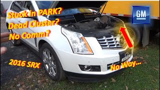
On the first-generation Cadillac SRX, this communication code is specifically mentioned in GM Technical Service Bulletin #PIC5460B in relation to a no-crank condition or the key being stuck in the ignition. This elevates it from a minor glitch to a potentially stranding issue. The problem is often rooted in the complex electrical architecture of this luxury SUV, where a single point of failure in the power supply (like the battery terminal fuse block), 🎬 Watch: Troubleshooting a dead cluster and no-start condition. a data line (the Class 2 wire, CKT 1807), or the BCM itself can cascade into multiple, seemingly unrelated symptoms.
Diagnostic Flowchart
Tap your situation to follow the diagnostic path that matches what you're seeing on this vehicle.
Symptoms You May Notice
- Vehicle will not crank or start.
- Key is stuck in the ignition lock cylinder.
- Instrument cluster is blank or gauges are inoperative.
- Warning lights for various systems (ABS, Airbag, Security) may illuminate.
- Power windows, locks, or interior lights do not work.
- Scan tool is unable to communicate with multiple modules, or only communicates with a few.
- Message display shows "UNKNOWN DRIVER".
- Parasitic battery drain that kills the battery overnight.
- Doors may lock and unlock repeatedly on their own.
- Replacing the Engine Control Module (ECM). The ECM is usually the module *reporting* the code, not the cause of it. The U1064 indicates the ECM has lost communication *with* the BCM. TSB PIC5460B advises suspecting the ECM only after all wiring and relays are confirmed good.
- Replacing the ignition switch. While symptoms like a stuck key might point to the switch, the root cause is often the BCM not sending the correct signal to release it due to the communication failure, as described in TSB PIC5460B.
Most Likely Causes
- Weak Battery or Poor Power/Ground Connections 🔴 High Probability Control modules require stable voltage (typically above 12.4V) to communicate properly. Low voltage from a weak battery or a bad ground is a frequent cause for modules to drop off the network and trigger communication codes.
How to confirm: Load test the battery to ensure it's healthy. Clean the battery terminals and check that the main ground straps to the chassis and engine block are clean, tight, and free of corrosion. Check the BCM ground G202 (left side of center console) and G104 (under the battery).
Typical fix: Replace the battery if it fails a load test. Clean or tighten all primary power and ground connections.
Est. part cost: $150-$300 - Faulty Body Control Module (BCM) 🔴 High Probability → Shop Body Control Module The BCM is the central hub for the Class 2 network and acts as the gateway. An internal failure can prevent it from sending its required status messages or cause it to short the data line, causing other modules to set a U1064 code.
How to confirm: This requires professional diagnosis. A technician will use a scan tool to see if the BCM is responsive. If the BCM has proper power (e.g., at fuse TBC1 #31) and ground but is not communicating, it has likely failed. They may isolate it at splice pack SP205 to confirm it's the module pulling the network down.
Typical fix: Replace the Body Control Module. The new module must be programmed to the vehicle's VIN and specific options using dealer-level software.
Est. part cost: $250-$500 - Poor Connection at Battery Fuse Block 🟡 Medium Probability There is a documented issue where a poor internal connection at the main 60-amp fuse on the positive battery terminal assembly causes a widespread loss of power to multiple modules, leading to a no-start and no-communication condition. This can be caused by corrosion or simple looseness of the securing nuts.
How to confirm: With the battery disconnected, carefully inspect the main fuse block on the positive battery terminal. Check for corrosion, looseness, or signs of heat/melting at the nuts securing the large fuses. A voltage drop test across the fuse terminals with the system under load will reveal a bad connection.
Typical fix: Clean the contacts and tighten the securing nuts. If the assembly is corroded or damaged, it must be replaced.
Est. part cost: $50-$150 - Open or Short in Class 2 Data Wire (CKT 1807) 🟡 Medium Probability The Class 2 network is a single-wire bus (typically a purple wire). 🎬 See this guide on GM Class 2 data line diagnosis. A break or short to ground/power in this wire anywhere in the vehicle will bring the entire network down. TSB PIC5460B specifically calls out checking CKT 1807 for opens or shorts when U1064 is present with a no-start.
How to confirm: A technician can test for signal activity on Pin 2 of the diagnostic port with an oscilloscope. A healthy signal is a square wave switching between 0 and 7 volts. If the signal is missing or stuck high/low, they will begin isolating modules at splice pack SP205 to find the source of the fault.
Typical fix: Repair the damaged section of the wiring harness.
Est. part cost: $5-$20 in wiring supplies
Rare But Worth Checking
- Faulty Dash Integration Module (DIM) / Instrument Cluster: The instrument cluster is an active module on the data bus. An internal fault in the cluster can disrupt network communication and cause other modules to set codes. In some cases, a faulty IPC can cause a no-start condition and must be replaced and programmed.
- Aftermarket Accessories: Improperly installed aftermarket equipment (remote starters, alarms, stereos) that tap into the vehicle's Class 2 data wire can disrupt communication and cause a flood of U-codes. This is a common source of intermittent electrical gremlins.
- Poor Connection at Transmission Connector (X1): TSB PIC4740F notes that unseated pins or corrosion in the 16-way transmission X1 connector, located on the side of the transmission, can cause various communication DTCs, including loss of communication with the BCM. This should be inspected if multiple U-codes are present.
- Water Intrusion from Clogged Sunroof Drains: On SRX models, the front sunroof drain hoses were known to be too short, causing them to detach from the cowl and drain water directly onto the passenger floorboard. This water can damage the BCM, which is located in the passenger footwell/center console area, leading to corrosion and communication failures. A special coverage program (NHTSA #10057201) was issued for this issue on later models, but the failure pattern can still occur on the 2004-2008 generation.
Diagnosis Steps
- Check Battery Health: Perform a load test on the battery and verify it is fully charged (above 12.4V) and healthy. Clean any corrosion from the terminals and main ground points.
- Inspect Main Fuses: Carefully inspect the main fuse block on the positive battery terminal for loose connections, corrosion, or damage, as this is a known failure point.
- Scan for All Codes: Use a full-featured scan tool to check for DTCs in ALL available modules. Note which modules are reporting U1064 and which are not communicating at all.
- Check BCM Fuses: Check all fuses related to the Body Control Module (BCM) and Instrument Panel Cluster (IPC). Specifically check the TBC1 fuse (#31 in the underhood fuse box) for the BCM's main power.
- Check Class 2 Data Line: A professional will test the Class 2 data line (Pin 2 at the DLC, purple wire) with a multimeter or oscilloscope to check for signal. A healthy signal toggles between 0V and 7V. A steady 0V or 12V indicates a shorted wire or module.
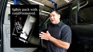
- Isolate Modules at Splice Pack: Locate splice pack SP205 (under the driver's side dash near the steering column). Disconnect the comb connector and use a jumper wire to connect the DLC pin to each module's pin one by one, checking the scan tool each time to see which module, when connected, causes the network to crash.
- Follow TSB PIC5460B: If a no-start is present, specifically check the integrity of the Ignition 1 Power Feed (CKT 5290) and the Class 2 data line (CKT 1807) between the fuse block and the ECM.
Parts You'll Likely Need
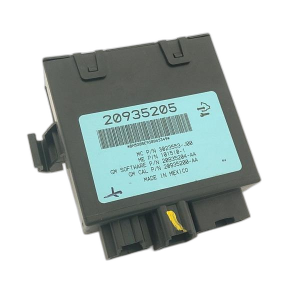
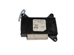
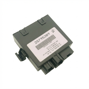
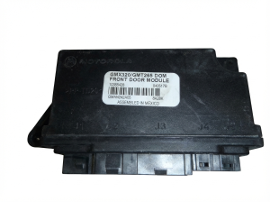
- Body Control Module (BCM)
(OEM #12245383 (2004-2006))— This is the most common module to fail and cause a U1064 code, leading to a no-start and various electrical issues. It acts as the network gateway and its failure can bring down communication.
Trusted brands: ACDelco (GM Genuine), Dorman (Remanufactured, 502-001), Cardone (Remanufactured, 73-1754)
Related Codes That Often Appear With This One
- U1000 — U1000 is a general Class 2 Communication Malfunction code. It is often stored alongside more specific codes like U1064 when a network-wide issue is present.
- U0100 — This code means Lost Communication with ECM/PCM. It can be set in other modules (like the BCM or TCM) when the entire network goes down, or if the ECM itself is the problem. TSB PIC5460B notes this code may be stored in other modules during a U1064 event.
- P1629 — This is a Theft Deterrent System code. The BCM is integral to the anti-theft system, and a communication failure prevents the ECM from getting the proper security clearance, triggering this fault and a no-start condition.
Technical Service Bulletins (TSBs) & Recalls
- No Crank, Key Stuck in Ignition, Multiple DTCs: This is the primary TSB for this issue. It directly links a no-crank or key-stuck-in-ignition symptom with code U1064 (and others like P1629, U1000). It guides technicians to investigate an open or short in the Ignition 1 Power Feed (CKT 5290) or the Class 2 data line (CKT 1807) going to the ECM. It suggests checking the main powertrain relay and the ECM itself only after wiring has been ruled out.
- No Crank, Multiple Warning Lights, Hard Shifting: This TSB applies to the SRX, CTS, and STS. It points to unseated pins or corrosion in the main transmission connector (X1) as a potential cause for a host of communication DTCs, including U0140 (Lost Communication with BCM). While not U1064 specifically, a BCM communication loss can trigger U1064 in other modules. The recommended fix is to inspect and repair the connections at the X1 plug.
Platform-Specific Known Issues
- BCM Location and Access: On the 2004-2008 SRX, the Body Control Module (BCM) is typically located behind the passenger side of the dashboard, often requiring removal of the glove box and lower dash panels for access. Its connectors should be checked for any signs of corrosion or looseness.
- 'UNKNOWN DRIVER' Message: A common and specific symptom of this communication failure on GM vehicles of this era is the message 'UNKNOWN DRIVER' appearing on the Driver Information Center (DIC). This indicates the BCM, which manages driver profiles and security, is offline.
- Splice Pack Location for Diagnostics: The Class 2 network uses a star configuration with central splice packs. Splice Pack SP205 is a key diagnostic point and is located under the left side of the instrument panel, near the data link connector. A technician can disconnect modules here one by one to isolate the source of a network failure.
Mechanic-Grade Diagnostic Values
- Class 2 Data Line Voltage (CKT 1807 at DLC Pin 2) — expected: A toggling square wave between approximately 0V (inactive) and +7V (active).. Failure: A steady 0V indicates a short to ground. A steady voltage near battery voltage (10-12V) indicates a short to power. A voltage that doesn't return to near 0V (e.g., rests at 287mV) can indicate a grounding issue or a partially shorted module.
- Module Power and Ground — expected: Battery voltage (12.4V+) at the BCM's main power fuses (e.g., TBC1 #31) with key on. Less than 0.1V (100mV) between the BCM's ground pins and a known good chassis ground.. Failure: Low or no voltage on the power side indicates a fuse or wiring issue upstream. High voltage on the ground side (voltage drop) indicates a bad ground connection.
Scan Tool Commands That Help
- GM Tech 2 / GDS2: Module Status / Class 2 Message Monitor — After finding a general U1000 or U1064, this function allows a technician to see which modules are actively sending their State of Health (SOH) messages on the network. If the BCM is absent from this list, it confirms it is the non-communicating module.
- GM Tech 2 / GDS2: Output Control / Bidirectional Tests — If the BCM is communicating, a technician can use bidirectional controls to command functions like door locks, lights, or the horn. If the BCM receives the command but the component doesn't actuate, it points to an output driver failure in the BCM or a wiring issue to that component, rather than a network-wide failure.
Wiring & Ground Locations
- SP205 — Located under the driver's side of the instrument panel, typically near the steering column. It's a black connector block where multiple purple Class 2 data wires converge.. This is the primary diagnostic point for the Class 2 network. By removing the comb that connects all the circuits, a technician can isolate each module one by one to see which one is shorting the network and causing the communication loss.
- G202 — On the left side of the center console, near the floor.. This is a primary ground point for several interior modules, including potentially the BCM. A loose or corroded G202 can cause intermittent communication issues and a host of seemingly unrelated electrical problems.
- BCM Location — Inside the vehicle, typically integrated into or near the center console/passenger footwell area. Access often requires removing trim panels around the glove box or console.. Knowing its location is critical for checking its power/ground connections and for replacement. Its location also makes it vulnerable to water damage from clogged sunroof drains or A-pillar leaks.
- G104 — Under the battery tray in the rear cargo compartment.. This is a major chassis ground point. While the battery ground itself is critical, corrosion at G104 can also introduce electrical noise and intermittent issues for modules located in the rear of the vehicle.
Real Owner Repair Stories
- Cadillac Forum user 'Evan Rea' (2005 Cadillac SRX) — Intermittent no-start condition. Lights and radio work, but turning the key does nothing. Problem would sometimes resolve itself after waiting.
❌ Tried (didn't work) Replacing the 'computer relay' worked for a week, then the problem returned.
✅ What actually fixed it The starter relay was faulty. Replacing the starter relay resolved the no-crank issue permanently. - GMTNation forum user (2004 GMC Envoy (similar GMT360 platform)) — No crank, no start. Display showed "UNKNOWN DRIVER". Security light was on. Power windows and dome lights inoperative. Doors would lock and unlock repeatedly on their own. Multiple U-codes including U1064.
❌ Tried (didn't work) Checking battery voltage (was 12.65V), Passlock relearn procedure, Checking all fuses, Disconnecting battery for 30 minutes (worked temporarily), Cleaning BCM ribbon cable
✅ What actually fixed it The Body Control Module (BCM) was faulty and had to be replaced. The user suspected it from the beginning due to the wide range of body-related symptoms.
OEM Part Supersession History
Varies by year→Varies by year— Standard part updates and revisions.
Heads up: The BCM for 2004-2006 models (e.g., 12245383) is different from the one used in 2007-2009 models. They are not interchangeable. Always verify the part number for the specific year and VIN before ordering.
Model Year Variations Within This Range
- 2007-2009: The Body Control Module part number and potentially some wiring configurations changed for the 2007 model year refresh. While the diagnostic principles for U1064 remain the same, the specific BCM part needed for replacement is different from the 2004-2006 models.
Helpful Videos

We Have This Part in Stock

The information in this article is provided for general reference and educational purposes only. Vehicle specifications, procedures, and part compatibility can vary by production date, trim level, and region. Always consult your vehicle's factory service manual and verify part numbers before purchasing or performing repairs. Safety-critical components such as airbags, seat belts, and braking systems should be installed by a qualified professional.
- Cadillac SRX:
- 🧭 Diagnostic Flowchart
- 🎬 Helpful Videos
- 🛍️ Shop This Part
- What's Unique About the 2004-2008 Cadillac SRX
- Symptoms You May Notice
- Most Likely Causes
- Rare But Worth Checking
- Diagnosis Steps
- Parts You'll Likely Need
- Related Codes That Often Appear With This One
- Technical Service Bulletins (TSBs) & Recalls
- Platform-Specific Known Issues
- Mechanic-Grade Diagnostic Values
- Scan Tool Commands That Help
- Wiring & Ground Locations
- Real Owner Repair Stories
- OEM Part Supersession History
- Model Year Variations Within This Range
- 🎟️ Get 5% Off