
U1153 on 2004-2007 Cadillac CTS: No-Start & Communication Loss Causes
On a 2004-2007 Cadillac CTS, code U1153 almost always appears with other communication codes due to a wiring problem at the Engine Control Module (ECM). This causes a no-crank and/or a key stuck in the ignition. The fix is typically repairing the power or data wire to the ECM, not replacing the module itself.
- U1153 on a 2004-2007 CTS is a serious code, usually indicating a no-start condition is imminent or already happening.
- The problem is almost always a wiring fault affecting the Engine Control Module (ECM), as documented in TSB PIC5460B.
- Do not immediately replace expensive components like the ECM or starter. Diagnosis must begin with checking the ECM's power and data lines.
- Symptoms include a no-crank, a key stuck in the ignition, and multiple communication codes stored together.
- A simple check involves swapping the main/powertrain relay in the underhood fuse box with a known-good one.
What's Unique About the 2004-2007 Cadillac CTS
The first-generation CTS uses a single-wire communication protocol called Class 2. A specific GM Technical Service Bulletin (TSB #PIC5460B) directly links code U1153 and a cluster of other 'U' codes to a no-crank or key-stuck-in-ignition problem. The issue is so common that the bulletin points directly to intermittent opens in either the ECM's power supply wire or its single data wire as the primary culprits. The ECM is located on the front of the right (passenger side) valve cover, making the harness section leading to it a key area for inspection. This makes it a known wiring issue rather than a random module failure.
Diagnostic Flowchart
Tap your situation to follow the diagnostic path that matches what you're seeing on this vehicle.
Symptoms You May Notice
- Engine will not crank or start.
- Key is stuck in the ignition lock cylinder and cannot be removed.
- Multiple warning lights on the dashboard, such as the security, traction control (TC), and brake lights.
- Scan tool cannot communicate with the ECM or shows multiple 'Lost Communication' codes for various modules.
- Charging system warning or abnormally low voltage reading while running.
- Instrument cluster is dead or flickers when trying to start.
- Fuel gauge does not sweep or read when the key is turned to the 'ON' position.
- Replacing the starter motor because the engine won't crank. The starter is not receiving the command to engage due to the communication failure.
- Replacing the battery or alternator. While low voltage can cause issues, it won't fix a broken wire and is often a symptom of the communication failure, not the cause.
- Replacing the ignition switch or lock cylinder. The key being stuck is a symptom of the ECM not telling the solenoid to release it, which is caused by the communication loss.
Most Likely Causes
- Open or Intermittent Connection in ECM Power Feed (CKT 5290) 🔴 High Probability This specific circuit is identified in TSB #PIC5460B as a primary point of failure leading to these exact symptoms. The wire, typically Pink/Black, can chafe or break in the harness near the ECM or underhood fuse block.
How to confirm: Using a multimeter, check for battery voltage at the ECM fuse in the underhood fuse block. Then, with the key on, carefully back-probe the Pink/Black wire at Pin 19 of the ECM connector to ensure consistent battery voltage is present. Wiggling the harness while testing can expose an intermittent open.
Typical fix: Repair the open or short in the wire. This may involve repairing a chafed section or replacing a corroded terminal at the ECM or fuse block connector.
Est. part cost: $5-$20 - Open or Intermittent Connection in ECM Class 2 Data Line (CKT 1807) 🔴 High Probability This is the second primary cause listed in TSB #PIC5460B. If the ECM can't talk to other modules via this single Purple wire, the car's anti-theft and starting sequence will fail.
How to confirm: This is more complex. It involves checking for continuity on the Class 2 data wire (Purple) between Pin 48 at the ECM connector and the data link connector splice pack. An oscilloscope is the best tool to see if the 0-7 volt square wave data signal 🎬 Watch: Professional guide to GM Class 2 data line diagnosis. is present and correct on the line.
Typical fix: Locate and repair the break or short in the Class 2 serial data wire leading to the ECM.
Est. part cost: $5-$20 - Faulty Main/Powertrain Relay 🟡 Medium Probability → Shop Wiring Relay The TSB notes that an intermittent relay can cause the same power loss to the ECM as a bad wire. Relays are mechanical devices with a finite lifespan that can fail from heat and vibration.
How to confirm: Swap the main or powertrain relay in the underhood fuse box with an identical relay from a non-critical system (like the horn or rear defogger). If the car starts, the relay is bad.
Typical fix: Replace the faulty relay. A common OEM part number is GM 19116057.
Est. part cost: $15-$40
Rare But Worth Checking
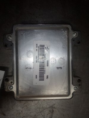
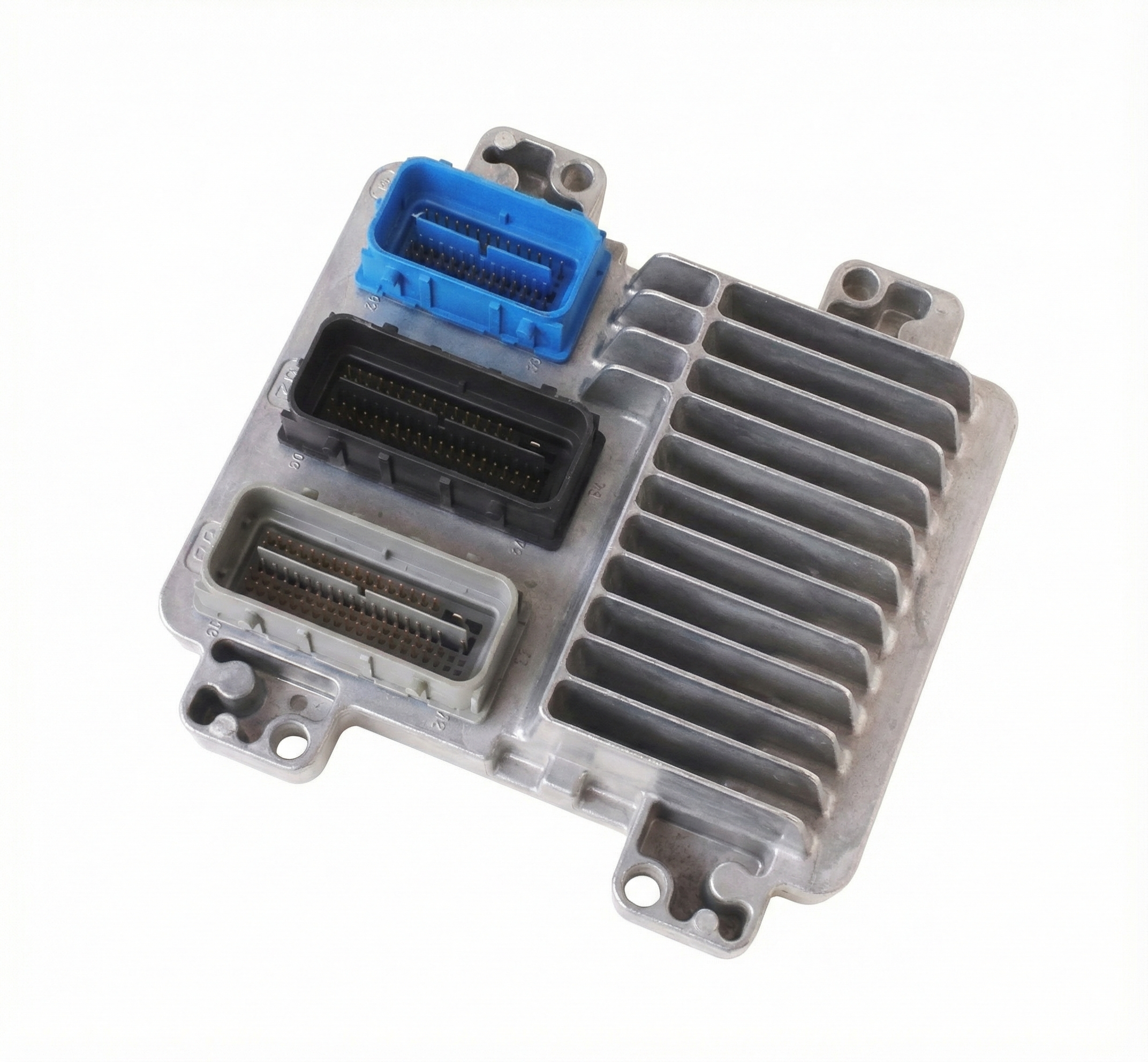
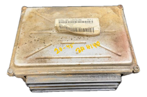
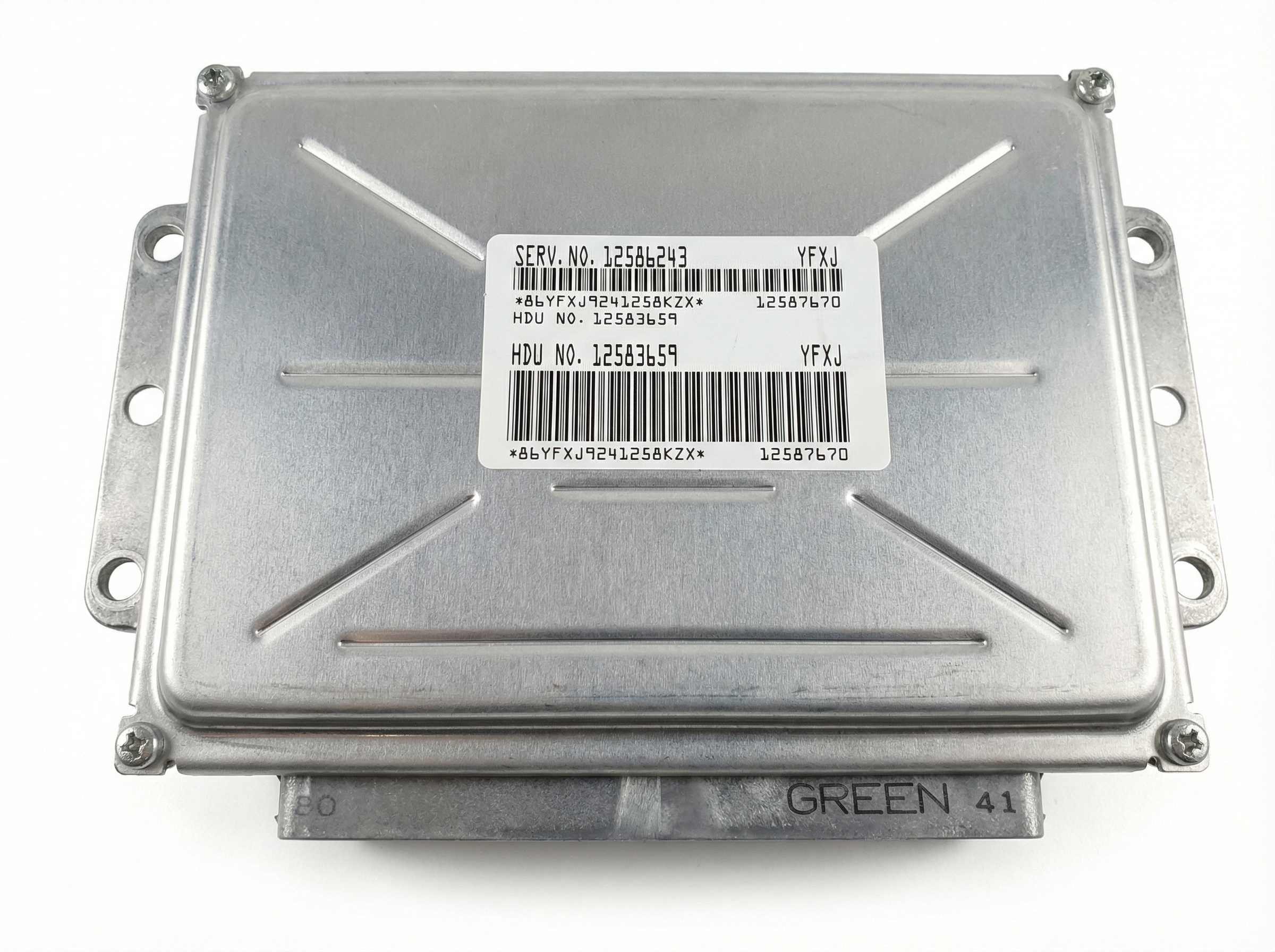
- Faulty Engine Control Module (ECM): → Shop Engine Control Module (ECM) The TSB lists this as a possibility only after all wiring and relay checks have been exhausted. It is much more likely to be a wiring issue feeding the ECM than the ECM itself.
- Unseated Pins in Transmission X1 Connector: A different TSB (#PIC4740 series) notes that poor connections at the main transmission harness connector can cause widespread communication codes on the Class 2 network. While not the primary cause for this specific symptom cluster, it's a known weak point on the platform worth checking if other transmission-related codes are present.
- Corroded Main Power Cable Fusible Link: In some cases, the main power cable running from the alternator has an inline fusible link that can corrode and break internally. This causes a 'Service Charging System' message and can lead to a no-start and widespread electrical issues due to low voltage, mimicking the U1153 symptoms. One owner documented this failure and repair on YouTube.
Diagnosis Steps
- Confirm symptoms: No-crank and/or key stuck in ignition.
- Perform a full vehicle scan and confirm the presence of U1153 along with multiple other U-codes, especially those listed in TSB #PIC5460B. Note if the scan tool fails to communicate with the ECM entirely.
- Locate the underhood fuse block. Check the 'ECM' or 'PCM' fuse. If it's blown, investigate for a short circuit. If it's good, proceed.
- With the key in the 'ON' position, measure the voltage at the ECM fuse. It should be battery voltage.
- Gain access to the ECM. On the first-gen CTS, it is located on the front of the passenger-side (right) valve cover.
- With the ECM connected and key 'ON', carefully back-probe the Ignition 1 Power Feed wire (CKT 5290, typically a Pink/Black wire at Pin 19) at the ECM connector. Verify it has consistent battery voltage. Wiggle the harness to check for intermittent opens.
- If power is missing or intermittent, trace CKT 5290 back to the fuse block, inspecting for breaks, chafing, or corrosion.
- If power is good, the next step is to inspect the Class 2 Data Line (CKT 1807, typically a Purple wire at Pin 48). Check for continuity between the ECM connector and the data link splice pack. An oscilloscope is the ideal tool to check for a healthy 0-7V square wave data signal.
- If wiring and connections to the ECM appear physically intact and test good, try swapping the 'RUN/CRANK' or 'PWR/TRN' relay with a known-good relay of the same type (e.g., from the horn circuit).
- If the problem persists after all wiring and relay checks, the ECM itself may be faulty.
Parts You'll Likely Need
- Main/Powertrain Relay
(OEM #19116057 (ACDelco D1786C))— This is an easy and inexpensive part to swap as a diagnostic step before diving into complex wiring repairs.
Trusted brands: ACDelco, Bosch, Standard Motor Products
OEM price range: $25-$50
Aftermarket price range: $15-$40 - Engine Control Module (ECM)
(OEM #12592124, 19260507, 12596577 (Varies by year/engine, must match service number))— This is the last resort if all wiring and relays are confirmed to be good. The ECM is the brain of the system, and an internal failure can cause this issue.
Trusted brands: ACDelco (Remanufactured)
OEM price range: $300-$500
Aftermarket price range: $200-$400
Related Codes That Often Appear With This One
- P1629 — Theft Deterrent Fuel Enable Signal Not Received. The ECM isn't getting the 'OK' from the theft module to start.
- U1000 — Class 2 Data Link Malfunction. This is a general code indicating a problem on the entire communication network.
- U1040 — Lost Communication with Electronic Brake Control Module (EBCM).
- U1064 — Lost Communication with Body Control Module (BCM).
- U1192 — Lost Communication with Vehicle Theft Deterrent Module.
- U1300 — Class 2 Data Link Low or High. Indicates a problem with the data line's voltage.
Technical Service Bulletins (TSBs) & Recalls
- PIC5460B: No Crank, Key Stuck In Ignition Lock Cylinder, Multiple ECM Codes And U1000 Set In Class 2 Modules. This is the primary document identifying the cause and diagnostic procedure for this specific issue.
Platform-Specific Known Issues
- TSB #PIC5460B: The Definitive Guide: This TSB specifically details the condition of a no-crank/key-stuck issue caused by an intermittent open in the Ignition 1 Power Feed (CKT 5290, Pink/Black wire) or the Class 2 data line (CKT 1807, Purple wire) to the ECM. It is the primary document for diagnosing this exact issue on the CTS and SRX.
Mechanic-Grade Diagnostic Values
- Class 2 Serial Data Line Voltage (Oscilloscope) — expected: A square wave toggling between approximately 0V (recessive state) and 7.0-7.5V (dominant state).. Failure: Signal is stuck low (near 0V), stuck high, or biased by an incorrect voltage (e.g., 10V), indicating a short to ground, short to power, or a faulty module pulling the bus voltage up.
- Class 2 Serial Data Line Voltage (Multimeter) — expected: A fluctuating DC voltage, typically averaging below 3.5V. A multimeter is not ideal but can sometimes spot a line that is completely dead (0V) or shorted to a constant voltage.. Failure: A steady 0V or a steady voltage above 7V (e.g., battery voltage) indicates a hard fault on the line.
Scan Tool Commands That Help
- GM Tech 2 / MDI with Techline Connect: Service Programming System (SPS) - 'Program ECM' / 'Reprogram ECM' — This function is mandatory after replacing the Engine Control Module (ECM). It downloads the correct software and VIN to the new module, allowing it to communicate with the vehicle's other modules and immobilizer system.
- GM Tech 2: Tool Self Test (VCI, Keypad, CANdi) — Before starting complex network diagnostics, run the self-test to ensure the diagnostic tool itself is functioning correctly and not causing communication errors.
Wiring & Ground Locations
- G102 — On the engine block. For 3.2L/3.6L engines, it's often on the back of the right cylinder head. For the 5.7L V8, it's on the block near the generator/alternator. This is a primary ground for the ECM.. A poor connection at this primary ground can cause the ECM to malfunction or fail to power on, leading to a total loss of communication and a no-start condition.
- G101 — In the engine compartment, near the left front strut tower.. This ground point serves the ECM and Transmission Control Module (TCM). Corrosion or a loose connection here can cause communication issues for both modules.
- SP205 — A Class 2 data line splice pack located in the passenger compartment, near the Data Link Connector (DLC) under the driver's side dash.. This is a central hub where the data wires from multiple modules meet. It is the most critical diagnostic point for isolating a network fault. By removing the comb connector, a technician can test each branch of the data bus individually to find which module or wire is causing the disruption.
- SP206 / SP207 — SP206 is located under the steering column, and SP207 is under the left-hand cowl panel.. These are additional splice packs for the Class 2 network. If a fault isn't isolated at SP205, these locations may need to be checked depending on which modules are on the affected circuit branch.
Real Owner Repair Stories
- ScannerDanner Forum User (2006 Cadillac CTS 2.8L) — No crank, key stuck in ignition, scan tool will not communicate with ECM, U1000 code present in other modules.
❌ Tried (didn't work) Confirmed all powers and grounds at the ECM were good per the TSB. Confirmed continuity on the Class 2 data wire between the EBCM and ECM.
✅ What actually fixed it The final fix was not posted, but the diagnosis correctly identified the fault: the Class 2 serial data line had under 2 volts on it, indicating it was being pulled low or shorted. The next step discussed was isolating modules at the splice pack to find the source of the short. - YouTube video by 'JaboTheMechanic' (Cadillac CTS (year not specified, but 1st gen)) — No crank, no communication with the computer. A key symptom noted is the fuel gauge not sweeping up when the key is turned on.
❌ Tried (didn't work) The video focuses on diagnosis rather than failed parts.
✅ What actually fixed it The video explains that the cause is a loss of communication with the ECM and points to two critical checks: the main fuses for the ECM and the two ground wires directly at the ECM, one of which attaches to the side of the engine block.
OEM Part Supersession History
12581144→12592124— Standard part revision and update by the manufacturer.
Heads up: Both part numbers require VIN-specific programming upon installation using a tool like the GM Tech 2 and SPS software. An unprogrammed module will not allow the engine to start due to the vehicle anti-theft system.
Model Year Variations Within This Range
- 2004-2007: The physical location of the main ECM ground (G102) can vary slightly depending on the engine. For example, on a 2004 model, the 3.2L engine has G102 on the left rear side of the engine, while the 5.7L V8 has it on the block near the generator. Always verify the location with a model-year and engine-specific diagram.
- 2006-2007: For the CTS-V model, the engine changed from the LS6 to the LS2. Additionally, 2006-2007 models received steering wheel mounted stereo controls. These changes do not fundamentally alter the Class 2 communication diagnosis for code U1153 but may affect harness routing or adjacent components.
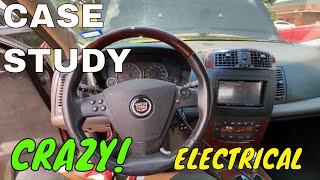
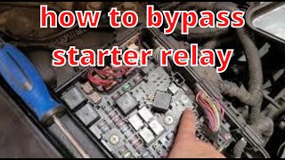
Helpful Videos


We Have This Part in Stock

The information in this article is provided for general reference and educational purposes only. Vehicle specifications, procedures, and part compatibility can vary by production date, trim level, and region. Always consult your vehicle's factory service manual and verify part numbers before purchasing or performing repairs. Safety-critical components such as airbags, seat belts, and braking systems should be installed by a qualified professional.
- Cadillac CTS:
- 🧭 Diagnostic Flowchart
- 🎬 Helpful Videos
- 🛍️ Shop This Part
- What's Unique About the 2004-2007 Cadillac CTS
- Symptoms You May Notice
- Most Likely Causes
- Rare But Worth Checking
- Diagnosis Steps
- Parts You'll Likely Need
- Related Codes That Often Appear With This One
- Technical Service Bulletins (TSBs) & Recalls
- Platform-Specific Known Issues
- Mechanic-Grade Diagnostic Values
- Scan Tool Commands That Help
- Wiring & Ground Locations
- Real Owner Repair Stories
- OEM Part Supersession History
- Model Year Variations Within This Range
- 🎟️ Get 5% Off