
U1192 on 2004-2007 Cadillac CTS: Lost Communication Causes and Fixes
On a 2004-2007 Cadillac CTS, code U1192 means the Engine Control Module (ECM) has lost communication with the anti-theft module (VTD). This is most frequently caused by a wiring issue or a bad ground, not a failed module. TSB #PIC5460B specifically points to opens/shorts in the Class 2 data line or ignition power feed to the ECM. Check engine bay grounds, ignition-related fuses, and the ECM wiring harness before replacing expensive components.
- U1192 is a network code indicating a communication breakdown with the anti-theft system.
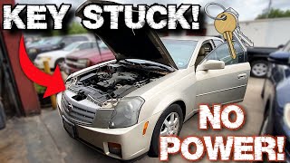
- Symptoms are severe, including a no-start condition and a key stuck in the ignition.
- The cause is most likely a wiring or ground fault, not an expensive computer module. Check grounds and fuses first.
- This code will almost always appear with other 'U' codes and P1629.
- Due to the complexity of network diagnostics, professional help is strongly recommended if simple checks don't resolve the issue.
What's Unique About the 2004-2007 Cadillac CTS
The first-generation Cadillac CTS relies on a single-wire communication network called the Class 2 data bus. Unlike modern CAN bus systems with redundant wiring, a single short or open circuit on this wire can disrupt communication between multiple essential modules. This is why a simple wiring fault often triggers a cascade of communication codes (like U1192, U1000, P1629) and seemingly unrelated symptoms like a stuck key, no-start, and dead accessories. The problem is rarely the expensive computer and more often the wiring that connects it, a fact emphasized by multiple GM Technical Service Bulletins.
Diagnostic Flowchart
Tap your situation to follow the diagnostic path that matches what you're seeing on this vehicle.
Symptoms You May Notice
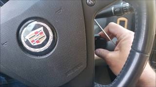
- Key is stuck in the ignition and cannot be removed.
- Engine will not crank or start (no-start condition).
- Security or anti-theft light is on or flashing.
- Multiple warning lights on the instrument cluster (TCS, ABS, etc.).
- Loss of power to interior components like the radio or HVAC controls.
- Transmission may shift harshly if the issue occurs while driving.
- Inability to communicate with the ECM or other modules using a basic scan tool.
- Charging system warning light may illuminate, with system voltage hovering around 12.5V while running.
- Replacing the ignition lock cylinder. While the key gets stuck, the mechanism is usually not the root cause; it's a symptom of the electrical failure that de-powers the key release solenoid.
- Replacing the battery or alternator. While a low battery can cause many electrical problems, if the battery tests good and the car still won't start and has these specific codes, the issue is more likely in the communication network or its supporting circuits.
Most Likely Causes
- Wiring Fault in Class 2 Data or Ignition Power Circuits 🔴 High Probability GM Technical Service Bulletin #PIC5460B directly identifies an open or short in the Class 2 serial data wire (CKT 1807) or the Ignition 1 Power Feed (CKT 5290) as a primary cause for a cluster of codes including U1192. The ECM wiring harness, particularly where it routes near the engine or through the firewall, is susceptible to moisture and physical damage.
How to confirm: Inspect the Class 2 serial data wire (CKT 1807, typically a Dark Green or Tan wire) and the Ignition 1 Power Feed (CKT 5290, typically a Pink/Black wire) for any signs of damage, corrosion, or looseness at the ECM connectors. A professional would use a multimeter to test for continuity and proper voltage at the ECM connector pins (specifically C1, Pin 59 for the Ignition 1 feed on a 2006 model), or an oscilloscope to verify the 0-7 volt square wave signal on the Class 2 data line.
Typical fix: Repair the damaged section of the wiring harness. This may involve soldering the wire, replacing a corroded pin, or securing a loose connector.
Est. part cost: $5-$20 - Poor or Corroded Ground Connection 🟡 Medium Probability Vehicle grounds, especially in the engine bay, are exposed to the elements and can corrode over time. A high-resistance ground on the engine block can cause a significant voltage drop, leading to bizarre electrical behavior and communication failures.
How to confirm: Locate and inspect the main engine and chassis ground straps. Key locations on the V6 models include G101 (near the left front strut tower) and G102 (back of the right cylinder head). A voltage drop test from the battery negative post to the engine block while attempting to crank should show minimal voltage; a high reading indicates a bad ground.
Typical fix: Disconnect the ground strap, clean the contact surfaces on the terminal and the chassis/engine block with a wire brush until shiny, and re-secure it tightly.
Est. part cost: $0-$5 - Blown Fuse 🟡 Medium Probability
How to confirm: Check the fuses in the rear fuse block (under the passenger side of the rear seat). Specifically, check the 10-amp fuse labeled 'RIM / IGN SW' (Rear Integration Module / Ignition Switch). A failure here is directly linked to the key getting stuck and can cause communication issues by cutting power to the ignition switch and key release solenoid.
Typical fix: Replace the blown fuse. If the fuse blows again immediately, it indicates a short circuit in the corresponding wiring that must be traced and repaired.
Est. part cost: $1-$10 - Unseated Pins in Transmission Connector (X1) ⚪ Low Probability TSB #PIC4740E (and its successors) notes that unseated pins in the main transmission harness connector can cause a flood of communication DTCs across the vehicle, including U-codes. The connector's location makes it vulnerable to moisture and vibration.
How to confirm: Disconnect the large X1 connector at the transmission and carefully inspect for any pins that are pushed back, corroded, or not fully seated. Gently tug on each wire to ensure it is secure, as a side load can create a false lock.
Typical fix: Reseat the loose pin or repair the connector terminal. Connector repair kits are available.
Est. part cost: $0-$25
Rare But Worth Checking
- Failed Engine Control Module (ECM): → Shop Engine Control Module (ECM) While possible, TSB #PIC5460B suggests this should only be suspected after all wiring, power, grounds, and relays have been thoroughly checked and confirmed to be good. A module failure can take down the communication bus, but it's far less common than a wiring problem. A technician confirmed this failure in one case only after verifying terminating resistance and wiring integrity.
- Failed Body Control Module (BCM) or Vehicle Theft (VTD) Module: Similar to the ECM, these modules can fail and disrupt communication. However, due to the cost and programming required, they should be considered a last resort after eliminating all wiring, power, and ground issues.
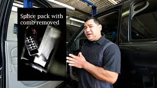
- Failed Main/Powertrain Relay: TSB #PIC5460B also mentions that an intermittent connection could be caused by a faulty main or powertrain relay that supplies power to the ECM. This can be tested by swapping the relay with a known good one of the same type. The ECM relay is often an ACDelco part #13503100. 🎬 See how a simple relay swap can fix a no-start.
Diagnosis Steps
- Perform a full system scan with a GM-compatible tool like a Tech 2 to retrieve all DTCs from all available modules. Note which modules are not communicating.
- Check the battery voltage and ensure it is above 12.4 volts. Perform a voltage drop test on the ground cables from the battery to the chassis and from the chassis to the engine block.
- Inspect all fuses in both the underhood and rear seat fuse blocks, paying close attention to the 10A 'RIM/IGN SW' fuse in the rear block and the main ECM/PCM fuses in the underhood block.
- Locate and inspect the main engine-to-chassis ground connections (G101 near the left strut tower, G102 at the back of the right cylinder head). Clean and tighten them as a preventative measure.
- Following TSB #PIC5460B, gain access to the ECM connectors. Visually inspect the wiring harness for damage, paying attention to areas near the underhood fuse box and where the harness routes under the radiator.
- With the key on, test for battery voltage at the Ignition 1 Power Feed (CKT 5290, Pink/Black wire) at the ECM connector C1, pin 59 (for 2006 models).
- Test the Class 2 data line (CKT 1807, Dark Green or Tan wire) for shorts to power or ground. A professional would use an oscilloscope on Pin 2 of the DLC to check for a proper 0-7 volt square wave signal, 🎬 Watch: Professional guide to diagnosing the Class 2 data line. which indicates healthy communication.
- If wiring, power, and grounds are confirmed good, the issue may be an internal failure of the ECM, BCM, or VTD module, requiring advanced diagnostics or component replacement.
Parts You'll Likely Need
- Wiring Repair Supplies — The most common cause is a break or short in a wire, which requires basic supplies like wire, solder, heat shrink, and electrical tape to repair.
OEM price range: $5-$20
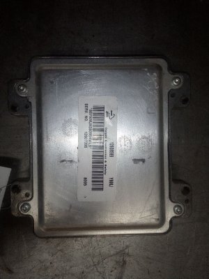
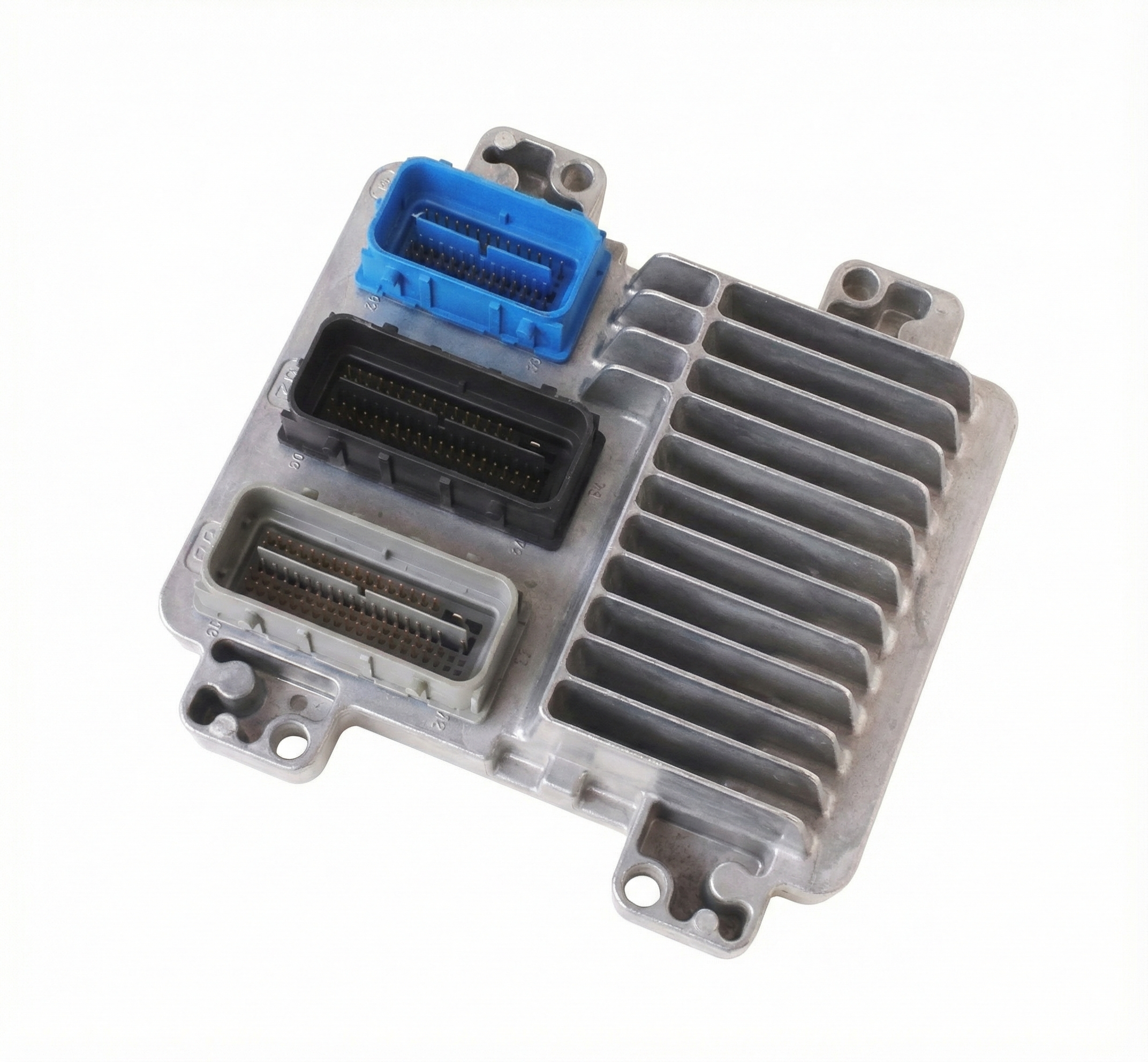
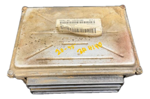
Aftermarket price range: $5-$20 - Engine Control Module (ECM)
(OEM #12592124, 12581144, 19260507)— This is a last resort after all wiring, power, and ground issues are ruled out. An internal ECM failure can bring down the entire communication network. Replacement requires VIN programming and a CASE relearn procedure.
Trusted brands: ACDelco (Remanufactured)
OEM price range: $300-$500
Aftermarket price range: $200-$400
Related Codes That Often Appear With This One
- P1629 — This code means 'Theft Deterrent Fuel Enable Signal Not Received'. It is a direct result of the ECM losing communication with the VTD module (U1192) and is almost always seen with it, as stated in TSB #PIC5460B.
- U1000 / U0100 — These are general 'Class 2 Data Link Malfunction' or 'Lost Communication with ECM' codes. They indicate a general network failure and often appear in multiple modules when a key module like the ECM goes offline or a central wiring fault occurs.
- U1040, U1064, U1153 — These are other 'Lost Communication' codes for the Electronic Brake Control Module (EBCM), Body Control Module (BCM), and HVAC system, respectively. They often appear in a group with U1192 when a central wiring or power issue disrupts the entire Class 2 network, as documented in TSB #PIC5460B.
Technical Service Bulletins (TSBs) & Recalls
- PIC5460B: Addresses a no-crank/key stuck concern with DTCs P0318, P1629, U1040, U1064, U1153, U1192, and U1300, pointing to wiring issues as the cause.
Platform-Specific Known Issues
- TSB #PIC5460B explicitly links a no-crank condition or a key stuck in the ignition with code U1192, pointing directly to wiring faults in the Ignition 1 Power Feed (CKT 5290) or the Class 2 data line (CKT 1807) as the cause.
- The placement of the ECM behind the driver's side front wheel well liner makes its connectors a known vulnerability to water intrusion and corrosion if the liner is damaged or missing, leading to these specific communication faults.
Mechanic-Grade Diagnostic Values
- Class 2 Serial Data Line Voltage — expected: A fluctuating square wave toggling between approximately 0V (inactive) and 7.0V (active).. Failure: The signal is stuck low (0V), stuck high, or biased by an incorrect voltage (e.g., 10V), indicating a short to ground, short to power, or a faulty module broadcasting incorrect voltage.
- Network Terminating Resistance — expected: Approximately 120 ohms when measured across the appropriate pins at the ECM or TCM.. Failure: A significantly different reading could indicate a wiring issue or a problem with the internal resistor in a terminating module.
Scan Tool Commands That Help
- GM Tech 2: Module Communication Status Check — This is a primary diagnostic step. After performing a full vehicle DTC scan, a technician can use the Tech 2 to see a list of all expected modules on the network and query their status. This quickly identifies which modules are offline (e.g., 'No Communication with ECM'), confirming the scope of the network failure and helping to pinpoint the source of the disruption.
- Professional Scan Tool: CASE Relearn (Crankshaft Angle Sensor Error) — This procedure is required after replacing the Engine Control Module (ECM). It synchronizes the new ECM with the crankshaft position sensor to prevent a P1336 trouble code from being set.
Wiring & Ground Locations
- G101 — In the engine compartment, near the left front strut tower.. This is a primary ground point for the Engine Control Module (ECM). A poor connection here can cause a loss of power or erratic behavior from the ECM, leading to network communication codes like U1192.
- G102 — On the back of the right cylinder head for 3.6L engines.. This is another critical engine ground. A bad ground here can introduce electrical noise and voltage drops that disrupt sensitive module communications.
- ECM C1, Pin 59 — On the larger of the two main connectors for the Engine Control Module.. On 2006 models, this pin is the Ignition 1 Voltage feed (Circuit 5290, Pink/Black wire). TSB #PIC5460B specifically calls out this circuit as a primary failure point. A technician must verify battery voltage at this pin with the key on to rule out a power supply issue to the ECM.
- DLC Pin 2 — The Diagnostic Link Connector (OBD-II port) under the driver's side dashboard.. This pin is the connection point for the Class 2 Serial Data line. An oscilloscope can be connected here to monitor the health of the entire communication network in real-time without having to access individual modules.
- Rear Fuse Block — Located under the passenger side of the rear seat cushion.. This block contains the 10-amp 'RIM / IGN SW' fuse that powers the ignition switch and the key release solenoid. A blown fuse here is a direct cause of the 'key stuck' symptom and can lead to power-up and communication issues.
Real Owner Repair Stories
- ADVANCED LEVEL AUTO YouTube Channel (2007 Cadillac CTS 3.6L) — Intermittent no-crank, key stuck in ignition, charging system not working (12.5V), multiple communication codes (U1000).
❌ Tried (didn't work) The shop the car was at could not diagnose it. The technician began by clearing codes and performing a full re-scan to identify hard faults.
✅ What actually fixed it The Engine Control Module (ECM) was faulty. This was determined after the technician performed a thorough diagnosis, confirming the Class 2 network terminating resistors at both the ECM and TCM were within spec (114-120 ohms) and checking powers and grounds, leaving the ECM itself as the only remaining possibility. - ADVANCED LEVEL AUTO YouTube Channel (2007 Cadillac CTS 3.6L) — Key stuck in ignition, car does not power up when key is turned, security light flashing.
❌ Tried (didn't work) The owner was using the manual key release to get the key out.
✅ What actually fixed it A blown 10-amp fuse labeled 'RIM / IGN SW' in the rear fuse block (under the rear seat). The technician traced the wiring diagram, identified the fuse as the power source for both the ignition switch and the key lock solenoid, and found it had no power. Replacing the fuse restored all functions. - LS1TECH Forum User (2006 Cadillac CTS-V) — Odd misfire and electrical issues after a car wash.
✅ What actually fixed it While not a final confirmed fix, a senior member advised the owner to immediately check the two large connectors next to the underhood fuse box for water intrusion and to inspect the wiring harness where it routes under the radiator and plugs into the PCM, as these are known weak points for water damage causing such issues.
OEM Part Supersession History
12581144→12592124— Standard part revision and consolidation by the manufacturer.
Heads up: Part number 12592124 is a direct replacement for 12581144, 12588472, and 19260507. After installation, a CASE (Crankshaft Angle Sensor Error) Relearn procedure must be performed using a professional scan tool to prevent code P1336.
Model Year Variations Within This Range
- 2007 (3.6L LY7): The Engine Control Module (ECM) on some later models, specifically the 2007 3.6L, is located directly on top of the engine, making it very easy to access. This contrasts with other documentation and possible earlier model years where the ECM is located behind the driver's side front wheel well liner, which requires removing the wheel and liner for access. This location difference significantly changes the labor time for diagnosis and replacement.
Helpful Videos
We Have This Part in Stock

The information in this article is provided for general reference and educational purposes only. Vehicle specifications, procedures, and part compatibility can vary by production date, trim level, and region. Always consult your vehicle's factory service manual and verify part numbers before purchasing or performing repairs. Safety-critical components such as airbags, seat belts, and braking systems should be installed by a qualified professional.
- Cadillac CTS:
- 🧭 Diagnostic Flowchart
- 🎬 Helpful Videos
- 🛍️ Shop This Part
- What's Unique About the 2004-2007 Cadillac CTS
- Symptoms You May Notice
- Most Likely Causes
- Rare But Worth Checking
- Diagnosis Steps
- Parts You'll Likely Need
- Related Codes That Often Appear With This One
- Technical Service Bulletins (TSBs) & Recalls
- Platform-Specific Known Issues
- Mechanic-Grade Diagnostic Values
- Scan Tool Commands That Help
- Wiring & Ground Locations
- Real Owner Repair Stories
- OEM Part Supersession History
- Model Year Variations Within This Range
- 🎟️ Get 5% Off