
U2100 on 2013-2015 Cadillac ATS: CAN Bus Communication Failure Causes and Fixes
On a 2013-2015 Cadillac ATS, code U2100 almost always points to a poor connection at the main transmission electrical connector (X1). Inspecting and securing the pins in this connector, as outlined in GM Technical Service Bulletin PIC4740F, is the most common fix and often costs nothing in parts. A chafed harness in the same area is the second most likely cause.
- U2100 on a 2013-2015 ATS is a serious network communication error, not a failure of a single part.
- Before any other diagnosis, check the battery voltage and perform a load test.
- The most probable cause is a poor connection at the main transmission connector (X1). A simple 'tug test' on the wires can often find the fault.
- Inspect the wiring harness for chafing, especially on the passenger side near the transmission.
- Do not replace expensive control modules unless all wiring and connection checks have been completed by a qualified technician.
What's Unique About the 2013-2015 Cadillac ATS
The 2013-2015 ATS, along with other GM vehicles from the same era, is specifically known for a wiring issue that causes this code. A widely-circulated Technical Service Bulletin (TSB), PIC4740F (which supersedes PIC4740E), points directly to the main transmission harness connector (known as X1) as the culprit. The female terminals inside this connector can become loose or make poor contact, leading to a network-wide communication failure that logs U2100 and a cascade of other seemingly unrelated codes.
Diagnostic Flowchart
Tap your situation to follow the diagnostic path that matches what you're seeing on this vehicle.
Symptoms You May Notice
- Multiple warning lights on the dash, such as 'Service Engine Soon', 'Service Stabilitrak', or 'Service Transmission'
- Transmission shifts harshly or feels like it's in the wrong gear
- Engine enters 'Reduced Power' mode
- Vehicle will not crank or start intermittently
- Scan tool cannot communicate with the ECM or TCM
- Door locks cycle on their own while driving
- Gauges on the instrument cluster drop to zero momentarily while driving
- Replacing the Transmission Control Module (TCM) or Engine Control Module (ECM) without first thoroughly inspecting the X1 connector and related wiring.
- Replacing individual sensors (like wheel speed sensors) based on other codes that appear alongside U2100, without realizing they are symptoms of the network failure, not the cause.
- Replacing the battery or starter for a no-crank symptom without first checking for communication codes that point to a network fault.
Most Likely Causes
- Loose or Damaged Terminals in Transmission Connector (X1) 🔴 High Probability → Shop Transmission Assembly This is a well-documented failure point identified by GM in Technical Service Bulletin PIC4740F. The female terminals within the connector can lose tension or become unseated over time due to vibration and thermal cycles. The TSB warns that a side load on the wires during assembly can create a 'false positive lock' that comes loose later.
How to confirm: Locate the X1 connector on the transmission. Disconnect it and visually inspect for corrosion or damage. Perform a 'tug test' by gently but firmly pulling on each individual wire at the back of the connector to ensure it is fully seated and locked in place. This is the most critical diagnostic step.
Typical fix: Reseat any loose terminals until they click. If a terminal is damaged or corroded, it may need to be replaced. In some cases, the entire connector pigtail may need to be spliced in. 🎬 See this guide on inspecting and testing transmission connector pins.
Est. part cost: $0-$75 - Chafed Wiring Harness 🟡 Medium Probability TSB PIC4740F specifically calls out an inspection for the ATS at the harness securing bracket on the passenger side of the transmission bell housing, where the harness can rub through against the bracket or engine block.
How to confirm: Visually inspect the wiring harness in the area where it is secured to the engine/transmission. Look for any signs of rubbing, exposed copper wire, or damage to the loom. This may require removing the bracket for a full view.
Typical fix: Repair the damaged wires using solder and heat shrink. Re-route or protect the harness with anti-abrasion tape or conduit to prevent future damage. Ensure the harness hangs below the securing bracket as instructed by the TSB.
Est. part cost: $5-$25 - Weak or Failing Battery ⚪ Low Probability → Shop Vehicle Battery Modern vehicles are highly sensitive to voltage. A battery that provides enough power to start the engine may still have low enough voltage during cranking to cause communication modules to glitch and set network codes.
How to confirm: Have the battery professionally load-tested, even if it seems fine. A simple voltage check is not sufficient. The voltage should be stable and above 12.4V at rest.
Typical fix: Replace the battery if it fails a load test.
Est. part cost: $150-$300
Rare But Worth Checking
- Poor Module Ground: A loose or corroded ground connection for a major module like the BCM or ECM can cause intermittent and hard-to-diagnose network issues. TSB PI1097A notes the importance of clean grounds on the ATS platform. Key grounds to inspect are G101 (ECM/TCM) and G103 (BCM/DLC).
- Failed Control Module: While less common than wiring issues, a control module (like the BCM, EBCM, or TCM) can fail internally and disrupt the entire network by constantly broadcasting corrupt data. This is typically a last resort after all wiring and connections have been verified.
Diagnosis Steps
- Verify Battery Health: Perform a load test on the battery. Ensure system voltage is stable and above 12.4V with the engine off.
- Scan for All Codes: Use a professional scan tool to retrieve all codes from all modules. Note which modules are not communicating. 🎬 Watch: How to diagnose a TCM communication failure.
- Inspect Transmission X1 Connector: This is the highest priority step. Locate the main electrical connector on the transmission. Disconnect it and inspect the pins and terminals for any signs of corrosion, moisture, or physical damage.
- Perform Wire Tug Test: As described in TSB PIC4740F, gently but firmly tug on each wire leading into the back of the X1 connector. If any wire feels loose or pulls out, the terminal is unseated and is the likely cause of the fault.
- Inspect for Harness Chafing: Carefully examine the wiring harness, especially where it is secured to the engine/transmission. On the ATS, pay close attention to the securing bracket on the passenger side of the bell housing.
- Check CAN Bus Resistance: If no physical wiring faults are found, disconnect the battery and measure the resistance between Pin 6 (CAN High) and Pin 14 (CAN Low) at the OBD-II diagnostic port. A healthy network should read approximately 60 Ohms. A reading of 120 Ohms indicates a break in the circuit or a missing terminating resistor.
- Isolate Modules: If resistance is incorrect (e.g., 120 Ohms or 0 Ohms), it indicates a break in the wiring or a short. This requires advanced diagnostics, often involving disconnecting modules one by one to see when the correct resistance returns.
Parts You'll Likely Need
- Transmission Connector Pigtail
(OEM #ACDelco PT2712 / GM 13580113)— If the X1 connector housing is cracked or terminals are too corroded/damaged to be re-pinned, a new pigtail must be spliced into the harness. Note: GM part number 13584094 and Dorman 645-595 are often listed as cross-references for this part.
Trusted brands: ACDelco, Dorman
OEM price range: $50-$100
Aftermarket price range: $30-$75 - Connector Terminals / Pins — If only one or two wires are loose in the connector, it may be possible to replace only the metal terminals themselves without replacing the entire connector housing. This requires a special de-pinning tool.
Trusted brands: ACDelco
OEM price range: $5-$15 per terminal
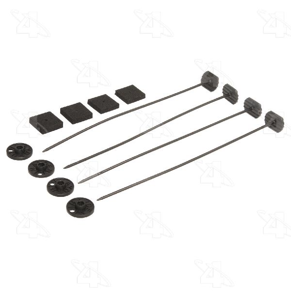
Aftermarket price range: $2-$10 per terminal - Anti-Abrasive Electrical Tape/Conduit — If the harness is found to be chafing, it must be repaired and then protected with high-quality loom or tape to prevent the problem from recurring.
Trusted brands: Tesa, 3M
OEM price range: $10-$20
Aftermarket price range: $5-$15
Related Codes That Often Appear With This One
- U0073 — Control Module Communication Bus 'A' Off. This is a generic CAN bus failure code that often appears with U2100.
- U0100 — Lost Communication With ECM/PCM. When the network is down, modules cannot talk to the engine computer.
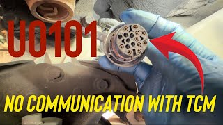
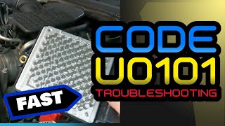
- U0101 — Lost Communication With TCM. This is extremely common with U2100 since the most likely fault location is the transmission connector itself.
- U0121 — Lost Communication With Anti-Lock Brake System (ABS) Control Module. The ABS/Stabilitrak system relies on the high-speed CAN bus and will log this code when it goes down.
- U0140 — Lost Communication With Body Control Module (BCM). The BCM is a central gateway for vehicle networks; a communication failure will almost always involve it.
- C0561 — System Disabled Information Stored. This is a generic code set by the ABS/Traction Control system indicating it has been disabled due to a fault, often a loss of communication.
- P0700 — Transmission Control Module (TCM) Requested MIL Illumination. The TCM sets this code to tell the ECM to turn on the Check Engine Light because a transmission-related fault (like a loss of communication) has occurred.
Technical Service Bulletins (TSBs) & Recalls
- PIC4740E (and its successor PIC4740F): Describes the primary cause of this code as unseated pins in the transmission X1 connector and/or a chafed harness, leading to multiple communication DTCs, hard shifting, and no-start conditions.
Platform-Specific Known Issues
- Owner Repair Story: The Loose Purple Wire: A well-documented case on cadillacforums.com involves a 2013 ATS owner whose car suddenly wouldn't start and displayed a cascade of communication codes (U0101, U2100, etc.). Following advice pointing to TSB PIC4740, the owner disconnected the X1 transmission connector. Upon performing a 'tug test' as instructed by the bulletin, a single purple wire pulled out of the connector with minimal force. After re-seating the terminal until it audibly clicked into place and reconnecting the harness, all communication was restored and the vehicle started normally. This is a classic example of the 'false positive lock' mentioned in the TSB.
Mechanic-Grade Diagnostic Values
- High-Speed CAN Bus Resistance — expected: ~60 Ohms. Failure: A reading of ~120 Ohms indicates an open circuit/terminating resistor fault. A reading near 0 Ohms indicates a short between the CAN High and Low wires.
- High-Speed CAN Bus Static Voltage (KOEO) — expected: CAN High (Pin 6 to ground): ~2.6V. CAN Low (Pin 14 to ground): ~2.4V.. Failure: Voltages stuck high (at battery voltage), low (at 0V), or equal to each other indicate a short to power, ground, or together.
- High-Speed CAN Bus Dynamic Voltage (Engine Running) — expected: CAN High (Pin 6 to ground): Oscillates ~2.5V to 3.5V. CAN Low (Pin 14 to ground): Oscillates ~2.5V to 1.5V.. Failure: A flat line or non-oscillating voltage on either line indicates a lack of communication or a bus fault.
Hidden / Shadow Codes Worth Checking
- Symptom Codes (e.g., UXXXX 01, 02, 31): GM vehicles often store 2-digit symptom codes along with the main DTC that provide more specific details about the fault (e.g., short to voltage, short to ground, internal failure). These are not visible on all scanners. (see via A GM-specific scan tool like a Tech 2 or a modern equivalent running GDS2 (Global Diagnostic System 2) software is required to view these sub-codes.)
Scan Tool Commands That Help
- GDS2 (GM): Module Presence/Communication Status — This is a primary diagnostic screen to use when U-codes are present. It provides a list of all expected control modules and shows their communication status (e.g., 'Communicating' or 'Not Communicating'), immediately identifying which module has dropped off the network.
- GDS2 (GM): Clear All DTCs — After performing a physical repair (like reseating a connector or fixing a wire), this command is used to erase fault codes from all modules simultaneously. This verifies if the fix was successful or if codes immediately return.
Wiring & Ground Locations
- X1 Connector — The main 16-pin electrical connector on the vehicle's transmission housing.. This is the most common failure point for code U2100 on this vehicle, due to loose or unseated terminals as identified in TSB PIC4740F.
- G101 — Located at the lower front of the engine block.. This is a primary ground point for the Engine Control Module (ECM) and Transmission Control Module (TCM). A poor connection here can cause communication failures for both modules.
- G103 — Located on the cowl in the engine compartment, above the brake booster.. This ground serves the Body Control Module (BCM) and the Data Link Connector (DLC)/OBD-II port. A fault here can prevent a scan tool from communicating and cause widespread network issues.
- G104 (2013 4-Cyl Models) — On early production models (before mid-Dec 2012), it's at the front of the engine. On later models, it was moved to the rear of the engine.. This is a key engine ground. Knowing its correct location for the specific vehicle build date is critical for an accurate inspection.
- DLC (OBD-II Port) Pins — Under the driver's side dashboard. Pin 6 is CAN High, Pin 14 is CAN Low. Pins 4 and 5 are grounds.. These are the primary test points for the entire network. Spread terminals at the DLC itself can cause intermittent communication issues, especially when a scan tool is connected.
Real Owner Repair Stories
- Paraphrased from multiple owner accounts and TSB PIC4740F (2013 Cadillac ATS) — No crank, no start, multiple warning lights on dash, scan tool shows U2100, U0100, U0101.
❌ Tried (didn't work) Replacing the battery, Checking fuses
✅ What actually fixed it Performed a 'tug test' on the wires at the X1 transmission connector. A single wire pulled loose. The terminal was re-seated firmly into the connector until it clicked. After reconnecting, all codes cleared and the car started normally. - Real repair story for a related platform with the same engine/transmission architecture. (Cadillac CTS (year not specified)) — No crank, no start, no communication with ECM/PCM. Low voltage (2V) measured at the underhood fuse box when using the engine block as a ground.
❌ Tried (didn't work) Initial diagnosis suspected a bad positive battery cable.
✅ What actually fixed it The main engine block ground cable was found completely broken off from its connection point on the vehicle frame. The engine was not properly grounded to the chassis. Re-attaching the ground cable restored proper voltage and fixed all symptoms.
"I Checked Everything" — The Actual Cause
- In the context of network codes, the equivalent is 'wiring checks out, but the fault persists.' A documented scenario involves a corroded ground strap for a different module (e.g., ABS) on the same ground circuit. The module's own electrical draw, unable to find a good path to ground, elevates the local ground potential, which injects electrical noise into the CAN bus and causes communication codes, even though the CAN wiring itself has proper resistance and is not shorted.
OEM Part Supersession History
PIC4740C, PIC4740D, PIC4740E→PIC4740F— Updates to the model years, DTC list, and instructions over time to address the ongoing transmission connector and harness chafing issue.
Heads up: Always use the latest version of the TSB for the most complete diagnostic information.
Model Year Variations Within This Range
- 2013 (Early Production): TSB PIC4740D specifically calls out 2013 ATS models built prior to 12/10/2012, suggesting an issue with early-build vehicles that may have been corrected on the assembly line later.
- 2013 (4-Cylinder Engines): The engine ground location (G104) was moved from the front of the engine to the rear of the engine starting in mid-December 2012. Verifying the correct ground location is important for vehicles built during this changeover period.
Helpful Videos
We Have This Part in Stock


The information in this article is provided for general reference and educational purposes only. Vehicle specifications, procedures, and part compatibility can vary by production date, trim level, and region. Always consult your vehicle's factory service manual and verify part numbers before purchasing or performing repairs. Safety-critical components such as airbags, seat belts, and braking systems should be installed by a qualified professional.
- Cadillac ATS:
- 🧭 Diagnostic Flowchart
- 🎬 Helpful Videos
- 🛍️ Shop This Part
- What's Unique About the 2013-2015 Cadillac ATS
- Symptoms You May Notice
- Most Likely Causes
- Rare But Worth Checking
- Diagnosis Steps
- Parts You'll Likely Need
- Related Codes That Often Appear With This One
- Technical Service Bulletins (TSBs) & Recalls
- Platform-Specific Known Issues
- Mechanic-Grade Diagnostic Values
- Hidden / Shadow Codes Worth Checking
- Scan Tool Commands That Help
- Wiring & Ground Locations
- Real Owner Repair Stories
- "I Checked Everything" — The Actual Cause
- OEM Part Supersession History
- Model Year Variations Within This Range
- 🎟️ Get 5% Off