
U2100 on 2008-2014 Cadillac CTS: CAN Communication Failure Causes & Fixes
On a 2008-2014 Cadillac CTS, code U2100 indicates a network communication failure. The most common cause is unseated pins or damage at the transmission X1 electrical connector, a known issue documented in GM Technical Service Bulletin PIC4740F. Inspecting and securing this connector, located on the transmission, should be your first step before suspecting faulty modules.
- U2100 on a 2008-2014 CTS means there is a general communication failure on the car's internal network.
- The most probable cause is a poor connection at the main transmission connector (X1), as documented in GM TSB PIC4740F.
- Symptoms are severe and can include a no-start, hard shifting, and multiple warning lights.
- Diagnosis should always start with a physical inspection of the transmission connector and nearby harness before replacing any expensive modules.
What's Unique About the 2008-2014 Cadillac CTS
While any vehicle can suffer from network issues, the second-generation Cadillac CTS has a well-documented weak point that frequently triggers code U2100 and other communication DTCs. GM issued a Technical Service Bulletin (TSB PIC4740 series) pointing directly to the transmission's main electrical connector (X1) as a common source of problems. Unseated terminals or chafed wires at this specific connector can disrupt the entire CAN bus, making it the first place to look rather than a last resort. The bulletin also 🎬 Watch: Troubleshooting a no-start caused by these communication issues. specifically calls out a harness securing bracket on the passenger side of the transmission bell housing as a potential chafe point on the CTS.
Diagnostic Flowchart
Tap your situation to follow the diagnostic path that matches what you're seeing on this vehicle.
Symptoms You May Notice
- Multiple warning lights on the instrument cluster (Check Engine, ABS, Stabilitrak)
- Transmission shifts harshly or gets stuck in one gear
- Vehicle will not crank or start
- Engine enters 'Reduced Power' mode
- Door locks cycle intermittently while driving
- Scan tool cannot communicate with the ECM or TCM
- Instrument panel cluster may self-test or gauges sweep when the diagnostic tool is plugged in
- Replacing the Transmission Control Module (TCM) or Engine Control Module (ECM) without first inspecting the transmission X1 connector. The problem is often the wiring or connector, not the expensive module itself.
- Replacing the battery or starter when a no-crank condition is present, without first checking for communication codes. A no-crank can be a symptom of the network failure, not its cause.
Most Likely Causes
- Loose or Corroded Transmission X1 Connector Terminals 🔴 High Probability → Shop HVAC Wiring Harness Connector Terminal This is a widely known issue documented by GM in TSB PIC4740E and its successor, PIC4740F. The connector's terminals can become unseated or corroded, disrupting network communication that passes through it. The bulletin notes that even a slight side load on the wires can cause a false positive lock, making the pins appear seated when they are not.
How to confirm: Visually inspect the transmission X1 connector. Disconnect it and gently tug on each individual wire to ensure the pins are fully seated and locked in place. Check for any signs of green or white corrosion, moisture, or backed-out pins.
Typical fix: Reseat any loose terminals. Clean any corrosion with electrical contact cleaner. If the connector housing or terminals are damaged, replace with a new connector pigtail. The connector is often a 16-pin black connector.
Est. part cost: $0-$70 - Chafed or Damaged Wiring Harness 🟡 Medium Probability TSB PIC4740F specifically calls out an inspection for the CTS: the harness near the passenger side of the transmission bell housing can chafe against a securing bracket, eventually exposing and shorting the CAN bus wires.
How to confirm: Inspect the wiring harness where it is routed near the passenger side of the transmission bell housing. Look for rub marks, exposed copper, or damage to the loom where it contacts the bracket.
Typical fix: Repair the damaged wires using solder and heat shrink. Re-route or protect the harness with anti-abrasion tape or loom to prevent future damage. Ensure the harness hangs below the bracket as intended.
Est. part cost: $5-$25 - Faulty Control Module ⚪ Low Probability While less common than the wiring issues, any module on the CAN network (BCM, ECM, TCM, etc.) can fail internally and disrupt communication. Water intrusion or voltage spikes are common causes of module failure.
How to confirm: This requires an advanced scan tool to see which module(s) are not communicating. A technician may disconnect modules one by one to see if communication is restored to the rest of the network. A faulty BCM is a common culprit for widespread communication issues. 🎬 See how a faulty BCM can disrupt the entire network.
Typical fix: Replace the faulty module (e.g., TCM, BCM, ECM) and program it to the vehicle.
Est. part cost: $200-$1000+ - Poor Ground Connection ⚪ Low Probability Corrosion can affect any ground point. A bad ground for a major module like the BCM or ECM can cause a host of communication errors.
How to confirm: Check the main battery, engine block, and chassis grounds for tightness and corrosion. A voltage drop test can confirm a bad ground. Forum users have noted that a group of ground wires tied to a single eyelet can corrode and melt, causing resistance.
Typical fix: Clean the contact surfaces of the ground point and wire terminal and re-secure tightly. If the eyelet or wires are damaged, they may need to be cut back and replaced.
Est. part cost: $0-$15
Rare But Worth Checking
- Spread Terminals in the OBD-II Diagnostic Link Connector (DLC):
Diagnosis Steps
- Perform a full vehicle scan to retrieve all DTCs from all modules. Note which modules are not responding.
- As per TSB PIC4740F, the primary step is to locate and disconnect the transmission X1 connector.
- Carefully inspect the connector for any signs of corrosion, moisture, or pushed-out/unseated pins.
- Gently tug on each individual wire going into the connector to ensure it is securely locked in place. The TSB warns that a side load on the wires can create a false positive lock.
- For the CTS specifically, inspect the wiring harness for any signs of chafing or damage where it passes a securing bracket on the passenger side of the transmission bell housing.
- If the connector and wiring appear intact, check the vehicle's main power and ground connections for tightness and cleanliness. Pay special attention to main ground points on the engine block and chassis.
- With the battery disconnected, use a multimeter to check for 60 ohms of resistance across the two CAN bus terminals at the OBD-II port (pins 6 and 14). A reading of 120 ohms suggests a break in the circuit or a missing terminating resistor; a reading near 0 ohms indicates a short circuit.
- If the issue persists, a professional will need to use an oscilloscope or advanced scan tool to isolate the faulty module or wiring section that is disrupting the network. This may involve disconnecting modules one by one to see when communication is restored.
Parts You'll Likely Need
- Transmission Connector Pigtail
(OEM #ACDelco PT2323 (88862242))— If the original 16-pin transmission connector housing or terminals are damaged beyond repair from corrosion or heat, a new pigtail is needed to restore a secure connection. This part number is a common replacement for this application.
Trusted brands: ACDelco, Dorman
OEM price range: $40-$70
Aftermarket price range: $20-$50
Related Codes That Often Appear With This One
- U0073 — This is an identical code for CAN Bus Communication Off, often set by a different module for the same root cause.
- P0700 — Indicates the Transmission Control Module (TCM) has requested the check engine light be turned on due to an internal fault, often triggered by its inability to communicate.
- U0100 — Lost Communication with ECM/PCM.
- U0101 — Lost Communication with TCM.
- U0121 — Lost Communication with Anti-Lock Brake System (ABS) Control Module.
- U0140 — Lost Communication with Body Control Module.
- C0561 — Indicates the Stabilitrak/Traction Control system has been disabled, often due to lost communication with the ECM or other necessary modules.
Technical Service Bulletins (TSBs) & Recalls
- PIC4740F: Successor to PIC4740E. Addresses conditions like no-crank, multiple warning lights, and hard shifting caused by unseated terminals in the transmission connector or a chafed
Platform-Specific Known Issues
- TSB PIC4740E and its successors identify unseated pins in the transmission X1 connector as a primary cause of widespread communication failures on this platform.
- TSB PIC4740F specifically adds an inspection step for the CTS and ATS models: check for harness chafing at a securing bracket on the passenger side of the transmission bell housing.
Mechanic-Grade Diagnostic Values
- CAN Bus Network Resistance — expected: Approximately 60 Ω (Ohms). Failure: A reading of ~120 Ω indicates an open circuit or a missing terminating resistor. A reading near 0 Ω indicates a short between the CAN High and Low wires. A reading of ~40 Ω may indicate an extra terminating resistor on the network, often from an aftermarket device.
- CAN High Voltage to Ground — expected: ~2.5V - 3.5V. Failure: Significant deviation from this range, or a voltage above 4.5V, can indicate a short to voltage.
- CAN Low Voltage to Ground — expected: ~1.5V - 2.5V. Failure: Significant deviation from this range can indicate a short or open in the CAN Low circuit.
Scan Tool Commands That Help
- Manual Diagnosis / Scan Tool: Isolate Bus by Disconnecting C3/X3 Connector — If the entire high-speed CAN bus is down, disconnecting the C3 (X3) connector at the instrument panel fuse block splits the network into two halves. This allows a technician to determine which half of the bus contains the fault (e.g., a shorted module or wire). If communication is restored to the BCM/TCM/ECM side, the fault is in the other half of the bus.
- Manual Diagnosis / Scan Tool: Isolate by Pulling Module Fuses — If a single module is suspected of internally shorting the CAN bus and bringing down the entire network, a technician can pull the power fuse for each module on the bus, one by one. When the fuse for the faulty module is pulled, communication may be restored to the remaining modules.
Wiring & Ground Locations
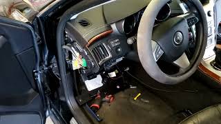
- Body Control Module (BCM) — Located under the driver's side dashboard, directly above the gas pedal.. The BCM is a central gateway module for multiple networks. A failure or poor ground to the BCM can cause widespread communication codes, including U2100. GM issued a bulletin warning technicians to always disconnect the battery before servicing BCM grounds to prevent module damage.
- G103 — A ground point located on the cowl in the engine compartment, above the brake booster.. This ground serves the Body Control Module (BCM), Instrument Panel Cluster (IPC), and the Diagnostic Link Connector (DLC) itself. Corrosion or a loose connection here can directly cause communication failures and an inability to scan the vehicle.
- Engine Block Ground — A heavy gauge cable connecting the engine block to the chassis/frame. One common failure point is a cable on the passenger side of the engine, sometimes near the A/C compressor, that can corrode and break.. The ECM and TCM are grounded through the engine block. If this main ground is broken, the modules lose their ground reference, causing them to go offline and triggering a no-crank and total communication loss. This can be misdiagnosed as a bad positive power cable.
- G303 — Located on the left (driver's side) B-pillar, behind the trim panel.. This is a body ground point. While not directly tied to the ECM in all diagrams, poor body grounds can cause intermittent and strange electrical issues that mimic module failures.
- C3 (X3) Connector — A green connector located on the back of the instrument panel (IP) fuse block.. This connector is a junction for the high-speed CAN bus. Disconnecting it is a key professional diagnostic step to split the network in half and isolate the source of a communication failure.
Real Owner Repair Stories
- YouTube user 'EuroweRx' (2011 Cadillac CTS) — No communication, no crank, no start. Multimeter showed an incorrect resistance value on the CAN bus instead of the expected 60 ohms.
❌ Tried (didn't work) Initial checks of the bus at the DLC showed an incorrect resistance, indicating a wiring fault.
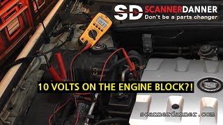
✅ What actually fixed it A CAN bus separation point/connector was found to be disconnected. After reconnecting it, the bus resistance measured a correct 61 ohms, and the vehicle was able to communicate and start. - YouTube user 'ScannerDanner' (Cadillac CTS (year not specified)) — Engine does not crank, multiple electrical issues. Low voltage (e.g., 2 volts) measured at the underhood fuse box when using the engine block as a ground reference.
❌ Tried (didn't work) Initial diagnosis pointed towards a bad positive battery cable due to the voltage drop at the front of the vehicle.
✅ What actually fixed it The main engine block ground cable was found completely broken off from its connection point on the frame. The engine block was not properly grounded to the chassis, causing the voltage drop. Re-establishing this ground connection restored proper voltage and fixed the no-crank condition. - YouTube user 'Jabo The Mechanic' (Cadillac CTS (year not specified)) — No crank, no start, no communication with the ECM/PCM when using a scan tool.
❌ Tried (didn't work) Attempting to start with the key results in nothing.
✅ What actually fixed it As a diagnostic bypass, the starter relay in the underhood fuse box was removed and the high-power terminals were jumped with a paperclip. This forced the starter to crank and the engine started, confirming the ECM/PCM was not commanding the starter to engage, likely due to the communication fault. This points to a fault in the control side (ECM, BCM, wiring) rather than the starter itself.
"I Checked Everything" — The Actual Cause
- A common diagnostic trap for a no-crank/no-communication issue is assuming the engine block is a good ground. In one documented case, voltage tests at the underhood fuse box showed very low voltage, suggesting a bad positive battery cable. However, the voltage was being measured relative to the engine block. When the multimeter's negative lead was moved to the chassis (strut tower), the voltage read a correct 12V. The actual cause was a completely broken main ground cable between the engine block and the frame. The block itself was 'floating' electrically, preventing the ECM and starter from operating correctly.
Helpful Videos
We Have This Part in Stock


The information in this article is provided for general reference and educational purposes only. Vehicle specifications, procedures, and part compatibility can vary by production date, trim level, and region. Always consult your vehicle's factory service manual and verify part numbers before purchasing or performing repairs. Safety-critical components such as airbags, seat belts, and braking systems should be installed by a qualified professional.
- Cadillac CTS:
- 🧭 Diagnostic Flowchart
- 🎬 Helpful Videos
- 🛍️ Shop This Part
- What's Unique About the 2008-2014 Cadillac CTS
- Symptoms You May Notice
- Most Likely Causes
- Rare But Worth Checking
- Diagnosis Steps
- Parts You'll Likely Need
- Related Codes That Often Appear With This One
- Technical Service Bulletins (TSBs) & Recalls
- Platform-Specific Known Issues
- Mechanic-Grade Diagnostic Values
- Scan Tool Commands That Help
- Wiring & Ground Locations
- Real Owner Repair Stories
- "I Checked Everything" — The Actual Cause
- 🎟️ Get 5% Off