
U2100 on 2007-2009 Cadillac SRX: CAN Bus Communication Failure Causes and Fixes
Code U2100 on a 2007-2009 Cadillac SRX indicates a network communication failure. This is most often caused by loose or corroded terminals in the main transmission electrical connector (X1), a known issue documented in GM Technical Service Bulletin PIC4740E and its successors. Inspecting, testing, and securing this specific connector is the most common and cost-effective fix before suspecting any module failures.
- U2100 on a 2007-2009 SRX is a network communication code, not a specific part failure.
- Before any other diagnosis, inspect the transmission X1 electrical connector for loose pins or corrosion, as this is the most common cause documented by GM.
- Symptoms are often severe and widespread, including a no-start, harsh shifting, and multiple warning lights.
- Do not replace expensive control modules (like the TCM or ECM) until you have ruled out wiring, connector, and power supply issues.
- This can be a difficult code to diagnose without the right tools, so professional help is recommended if the initial connector inspection doesn't solve the problem.
What's Unique About the 2007-2009 Cadillac SRX
While U2100 can be a generic network code on many vehicles, on the first-generation Cadillac SRX and its platform mates (like the STS and CTS), GM has identified a very common failure point. Technical Service Bulletin PIC4740E (and later revisions like F) specifically points to the main transmission harness connector (known as X1) as the primary culprit. The female terminals within this connector can lose tension or the wires can back out, causing an intermittent or total network-wide communication breakdown. This is the root cause of the U2100 code far more often than actual module failure.
Diagnostic Flowchart
Tap your situation to follow the diagnostic path that matches what you're seeing on this vehicle.
Symptoms You May Notice
- Check Engine Light (SES light) is on.
- Vehicle enters 'Reduced Power' mode.
- Transmission shifts harshly or seems stuck in one gear.
- Multiple warning lights on the instrument cluster (e.g., ABS, Stabilitrak, TCS).
- No-crank or no-start condition.
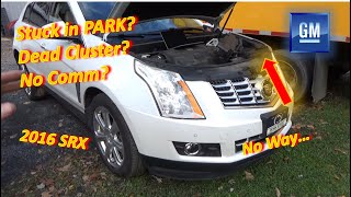
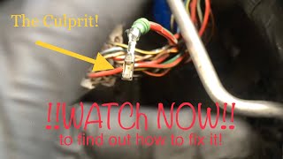
- Instrument cluster gauges behave erratically or go blank. 🎬 Watch: Troubleshooting a dead cluster and no communication issues.
- Scan tool cannot communicate with the ECM or TCM.
- Door locks cycle randomly while driving.
- Replacing the Transmission Control Module (TCM) or Engine Control Module (ECM) without first inspecting the X1 connector and related wiring.
- Replacing individual sensors when the root cause is a network-wide communication failure. 🎬 See how to fix common ECM communication errors for free.
- Ignoring a weak battery or failing charging system, which can mimic network faults.
- Replacing the transmission itself, when the issue is only the external electrical connector.
Most Likely Causes
- Loose or Corroded Transmission X1 Connector Terminals 🔴 High Probability → Shop HVAC Wiring Harness Connector Terminal This is a well-documented issue for this platform, as cited in GM TSB PIC4740E and its revisions. The connector's location on the transmission makes it susceptible to vibration and moisture over time, leading to poor pin connections and backed-out wires.
How to confirm: Locate the X1 connector on the driver's side of the transmission. Disconnect it and visually inspect for corrosion, moisture, or backed-out pins. Gently tug on each wire entering the back of the connector to ensure it is fully seated; the TSB warns that a side load can give a false positive lock. A 'pin drag test' using a matching male terminal is the definitive way to check for proper female terminal tension.
Typical fix: Clean the connector terminals with a specialized contact cleaner and apply dielectric grease. Reseat any loose wires by pushing them in until they click. If terminals have lost tension (failed a pin drag test) or the connector housing is damaged, a new connector pigtail must be spliced in. Terminal repair may be possible with a J-38125 kit.
Est. part cost: $10-$70 - Damaged Wiring Harness 🟡 Medium Probability Wiring harnesses can chafe against the engine block, transmission housing, or chassis components over time, leading to shorts or open circuits in the CAN bus wires. The TSB for platform mates like the CTS/ATS notes a specific chafe point near a harness bracket on the passenger side where the bell housing meets the engine block.
How to confirm: Visually inspect the wiring harnesses, particularly around the transmission, engine, and any points where the harness is secured by brackets. Look for worn-through insulation or signs of physical damage.
Typical fix: Repair the damaged section of wire using solder and heat shrink tubing. Secure the harness away from any sharp edges or moving parts.
Est. part cost: $5-$25 - Failing Battery or Alternator ⚪ Low Probability → Shop Vehicle Battery Modern control modules are sensitive to voltage. Low or unstable system voltage from a weak battery or failing alternator can cause modules to drop off the communication network, mimicking a CAN fault. GM has issued bulletins for other models where low voltage during cranking can set various communication codes.
How to confirm: Load test the battery to ensure it's healthy (should be above 12.5V at rest). With the engine running, check the voltage at the battery terminals; it should be stable, typically between 13.8V and 14.7V.
Typical fix: Replace the battery or alternator if they fail testing.
Est. part cost: $150-$500
Rare But Worth Checking
- Faulty Control Module (TCM, BCM, ECM): While possible, module failure is much less common than wiring or connector issues. A module should only be replaced after all wiring, connectors, and grounds have been thoroughly tested and confirmed to be good. This is the last step in diagnosis, not the first.
- Poor Ground Connections: A corroded or loose ground strap for the engine, transmission, or a specific control module can introduce electrical noise and disrupt CAN bus communication. Check major ground points on the frame and engine block. A key ground to inspect is G201, located in the upper left corner of the instrument panel near the A-pillar.
- Spread Terminals in the Diagnostic Link Connector (DLC): Another GM TSB (PIC5741B) notes that frequent use of aftermarket devices can spread the terminals in the vehicle's OBD-II port, causing poor connections with scan tools and sometimes setting communication codes. If you can't communicate with any modules, this is a possibility.
Diagnosis Steps
- Check and load-test the battery. Ensure system voltage is stable and within the 13.8-14.7V range with the engine running.
- Perform a full vehicle scan to see which modules are reporting 'no communication'. Note all stored DTCs.
- Following TSB PIC4740E, locate the main transmission electrical connector (X1) on the driver's side of the transmission.
- Disconnect the X1 connector. Thoroughly inspect the pins and terminals on both sides for green/white corrosion, moisture, or physical damage.
- Gently pull on each wire at the back of the connector to ensure they are fully seated and locked in place. The TSB specifically warns that wires can appear seated but not be locked.
- If a terminal test kit (like J-35616) is available, perform a pin drag test on the female terminals to check for proper tension. Loose terminals are a primary cause of this fault.
- If the connector and terminals are sound, inspect the wiring harness for any signs of chafing or damage, especially where it runs near the engine, transmission, and suspension components.
- If wiring is confirmed to be good, check for proper power and ground at the non-communicating modules using a wiring diagram.
- As an advanced step, use a multimeter to check for 60 ohms of resistance across pins 6 and 14 (CAN High and CAN Low) of the DLC with the battery disconnected. This verifies the integrity of the terminating resistors.
Parts You'll Likely Need
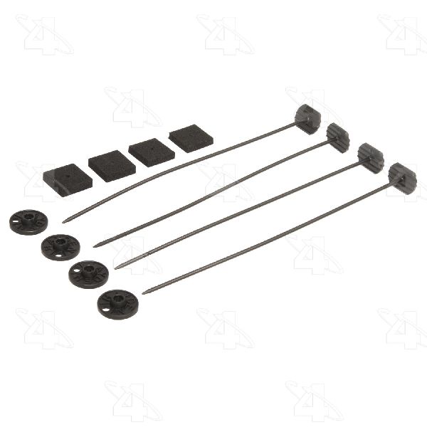
- Transmission Wiring Harness Connector Pigtail
(OEM #ACDelco PT2787 (Verify by VIN, multiple connectors used))— If the original X1 connector housing is damaged or terminals have lost tension beyond repair, splicing in a new pigtail is the standard, reliable fix.
Trusted brands: ACDelco, Dorman, Standard Motor Products
OEM price range: $40-$80
Aftermarket price range: $20-$50 - Electrical Contact Cleaner — Necessary for safely cleaning corrosion from connector pins without leaving a residue that could impede connection.
Trusted brands: CRC, WD-40 Specialist
OEM price range: $10-$15
Aftermarket price range: $8-$12 - Dielectric Grease — Applied to the connector after cleaning to seal out moisture and prevent future corrosion, which is crucial for connectors in exposed locations.
Trusted brands: Permatex, Loctite
OEM price range: $5-$10
Related Codes That Often Appear With This One
- U0073 — Another general CAN Bus Communication failure code, often set alongside U2100.
- U0100 — Indicates 'Lost Communication With ECM/PCM', a specific symptom of the general network failure.
- U0101 — Indicates 'Lost Communication With TCM', another specific symptom pointing towards the transmission area as the problem source.
- P0700 — This code means the TCM has requested the check engine light be turned on, which it will do when it detects a major internal or communication fault.
- C0561 — Indicates 'System Disabled Information Stored', often related to the Stabilitrak/ABS system losing communication with other essential modules.
- U2105 — Indicates 'Lost Communication With Engine Control Module (ECM)', often set with U2100.
- U2106 — Indicates 'Lost Communication With Transmission Control Module (TCM)', often set with U2100.
Technical Service Bulletins (TSBs) & Recalls
- PIC4740E: Addresses conditions like no-crank, harsh shifting, and multiple warning lights with code U2100. Recommends inspecting the transmission X1 connector terminals for loose or poor fit.
- PIC4740F: A superseding bulletin that expands the model list and reinforces the same diagnostic procedure for the X1 connector.
- 08-07-30-021H: A related TSB for other GM vehicles with 6-speed automatics that details procedures for diagnosing and repairing terminal and connector issues causing GMLAN communication loss, corroborating the repair methodology.
Platform-Specific Known Issues
- GM Technical Service Bulletin PIC4740E (and later revisions) explicitly identifies unseated pins in the transmission X1 connector as the primary cause for U2100 and a host of other communication codes on the 2007-2009 SRX.
Mechanic-Grade Diagnostic Values
- High-Speed GMLAN Bus Resistance — expected: Approximately 60 Ω. Failure: A reading of ~120 Ω indicates an open in the bus or a missing terminating resistor. A reading near 0 Ω indicates a short between the CAN high and low wires.
- CAN High Voltage — expected: ~2.7 V (average). Failure: Significant deviation from 2.7V can indicate a short to power or ground.
- CAN Low Voltage — expected: ~2.3 V (average). Failure: Significant deviation from 2.3V can indicate a short to power or ground.
Hidden / Shadow Codes Worth Checking
- U2100 (History): When a module detects a temporary bus-off condition, it may set U2100 as a history code, indicating an intermittent fault even if the network is currently communicating. (see via A professional scan tool like a GM Tech2 can retrieve history codes that may not be visible on basic OBD-II readers.)
Scan Tool Commands That Help
- GM Tech2 with CANdi Module: View All Modules / Network Scan — This is the first step to see which specific modules are reporting 'No Communication', which helps narrow down the physical location of the wiring fault.
- GM Tech2 / GDS2: Module Isolation Diagnostics — If a single module is suspected of corrupting the entire network, a technician can use the scan tool to monitor network status while physically disconnecting modules one by one until communication is restored to the others.
- GM Tech2 / GDS2: TCM Fast Learn — After replacing and programming a new Transmission Control Module (TCM), this bidirectional command must be run to perform transmission adaptations.
Wiring & Ground Locations
- DLC (Data Link Connector) — Under the driver's side dashboard, to the left of the steering column.. This is the primary access point for diagnostics. Pin 6 (CAN High) and Pin 14 (CAN Low) are used for network resistance and voltage tests.
- X1 Connector — The main 16-pin electrical connector on the driver's side of the transmission housing.. This is the most common failure point for U2100 on this vehicle, as identified in TSB PIC4740E. Loose or corroded terminals here break the CAN bus circuit.
- Terminating Resistors — Two 120-ohm resistors are on the bus. One is typically internal to the Engine Control Module (ECM). The other is at the opposite end of the high-speed bus, often in another module or a separate plug.. The integrity of both resistors is required for the bus to function. A 60-ohm reading across the bus confirms both are online.
- G201 — In the upper left corner of the instrument panel, near the A-pillar, behind the plastic dash trim.. This is a major ground point for the instrument panel and interior components. A poor connection here can cause erratic behavior of gauges and warning lights, which are common symptoms of a CAN bus failure.
OEM Part Supersession History
Varies by VIN→Varies by VIN— Connector design updates or supplier changes.
Heads up: Multiple pigtails like ACDelco PT2787 and PT787 exist and may look similar, but have different applications. Splicing the wrong connector can lead to immediate or intermittent faults. Always verify the correct part number using the vehicle's VIN before ordering a replacement X1 connector pigtail.
Helpful Videos
We Have This Part in Stock


The information in this article is provided for general reference and educational purposes only. Vehicle specifications, procedures, and part compatibility can vary by production date, trim level, and region. Always consult your vehicle's factory service manual and verify part numbers before purchasing or performing repairs. Safety-critical components such as airbags, seat belts, and braking systems should be installed by a qualified professional.
- Cadillac SRX:
- 🧭 Diagnostic Flowchart
- 🎬 Helpful Videos
- 🛍️ Shop This Part
- What's Unique About the 2007-2009 Cadillac SRX
- Symptoms You May Notice
- Most Likely Causes
- Rare But Worth Checking
- Diagnosis Steps
- Parts You'll Likely Need
- Related Codes That Often Appear With This One
- Technical Service Bulletins (TSBs) & Recalls
- Platform-Specific Known Issues
- Mechanic-Grade Diagnostic Values
- Hidden / Shadow Codes Worth Checking
- Scan Tool Commands That Help
- Wiring & Ground Locations
- OEM Part Supersession History
- 🎟️ Get 5% Off