
U2100 on 2006-2011 Cadillac STS: Causes and Fixes for CAN Bus Communication Failure
On a 2006-2011 Cadillac STS, code U2100 almost always indicates a communication network failure caused by loose or corroded pins in the main transmission harness connector (X1). Inspecting and securing this connector is the most common fix, as outlined in GM TSB PIC4740F.
- U2100 is a network code, not a specific part failure. Do not replace expensive modules until you have verified the wiring.
- The most likely cause on a 2006-2011 STS is a bad connection at the main transmission harness connector (X1).
- Symptoms can be widespread and confusing, from a no-start condition to hard shifts and multiple random warning lights.
- Always check the battery and charging system health first, as low voltage can mimic network problems.
- Diagnosing this code can be complex; professional help is recommended if you are not comfortable with electrical diagnostics.
What's Unique About the 2006-2011 Cadillac STS
For this specific generation of Cadillac STS and its platform mates, GM has identified a common failure point that causes the U2100 code. A Technical Service Bulletin (PIC4740E, later superseded by PIC4740F) points directly to the transmission harness connector, known as X1, as a frequent source of poor connections. The female terminals inside this connector can become loose or unseated, leading to a network-wide communication breakdown that triggers U2100 and a host of other seemingly unrelated error codes.
Diagnostic Flowchart
Tap your situation to follow the diagnostic path that matches what you're seeing on this vehicle.
Symptoms You May Notice
- Check Engine Light (SES) is on
- Multiple warning lights on the dash (ABS, Traction Control, Airbag)
- "Service Transmission" or similar messages displayed
- Harsh or erratic transmission shifting
- Engine runs in "Reduced Power" mode
- Vehicle may not crank or start 🎬 Watch: A real-world diagnosis of an STS-V no-start issue.
- Gauges (like temperature or fuel) may drop to zero intermittently
- Scan tool cannot communicate with one or more modules
- Door locks cycle while driving
- Replacing the Transmission Control Module (TCM) or another module without first checking the X1 connector and wiring harness.
- Replacing individual sensors when the root cause is a network-wide communication failure.
- Condemning the Engine Control Module (ECM) when a low battery voltage is the actual cause of the communication loss.
Most Likely Causes
- Loose or Damaged Terminals in Transmission Connector (X1) 🔴 High Probability → Shop Transmission Assembly A GM Technical Service Bulletin (PIC4740E, updated by PIC4740F) specifically identifies this as a primary problem for the 2006-2011 STS and related models. Vibrations and heat cycles cause the female terminals in the connector to lose tension or become unseated, failing to make a solid connection with the male pins.
How to confirm: Locate the main harness connector (X1) on the transmission. Disconnect it and visually inspect the pins for corrosion, moisture, or damage. Gently tug on each wire going into the back of the connector to ensure it is fully seated and locked in place; a side load can give a false positive lock.
Typical fix: Reseat any loose wires. If terminals are loose or corroded, they may need to be replaced using the proper terminal repair tools (e.g., J-38125 kit). A common repair is to splice in a new connector pigtail 🎬 See this walkthrough on how to handle the 6L80e connector. if the housing is damaged. Applying dielectric grease during reassembly helps prevent future moisture intrusion.
Est. part cost: $20-$120 - Damaged Wiring Harness 🟡 Medium Probability Wiring for the CAN bus runs throughout the vehicle and can be susceptible to chafing against chassis components or heat damage near the engine and exhaust. TSB PIC4740F notes that on some related models, the harness securing bracket near the bell housing can cause chafing.
How to confirm: Visually inspect the main wiring harnesses, especially where they pass near the engine, transmission, and through the firewall. With the battery disconnected, use a multimeter to check for 60 ohms of resistance between Pin 6 and Pin 14 of the OBD-II port. Wiggle the harness; if the resistance fluctuates wildly, you have a wiring issue.
Typical fix: Repair the damaged section of wire by soldering and using heat-shrink tubing. Secure the harness away from sharp edges or hot components.
Est. part cost: $1-$20 - Failing Battery or Alternator ⚪ Low Probability → Shop Vehicle Battery Modern vehicles are highly sensitive to voltage. An aging battery or weak alternator can provide inconsistent voltage below the normal operating range (approx. 12.6V-15V), causing modules to randomly drop off the communication network and set communication codes like U0100 or U2100.
How to confirm: Have the battery load-tested. A healthy battery should have over 12.5 volts at rest. With the engine running, check the voltage at the battery terminals; it should be stable and typically between 13.8 and 14.7 volts.
Typical fix: Replace the vehicle's battery or alternator.
Est. part cost: $150-$500
Rare But Worth Checking
- Failed Control Module: While possible, a module (like the TCM, BCM, or EBCM) is less likely to fail than the wiring connected to it. This should be considered only after all wiring and connection issues have been ruled out.
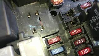
- Corrosion in Underhood Fuse Block: The main fuse block in the engine bay is another central point for electrical connections. Water intrusion or corrosion here can cause a variety of strange electrical issues, including communication faults. A visual inspection is warranted if other causes are not found.
- Poor Main Ground Connection: A corroded or loose main ground strap between the engine block and the chassis can cause a voltage potential difference between modules, disrupting CAN communication even if the battery and alternator are healthy. This can manifest as a no-crank or various communication faults.
Diagnosis Steps
- Perform a full vehicle scan to see which modules are not communicating and what other codes are present. Note all codes, as they provide clues to the origin of the fault.
- Check and load-test the battery to rule out voltage issues. Ensure terminals are clean and tight. Voltage should be above 12.5V.
- With the engine running, check alternator output voltage to ensure it's stable and within the 13.8-14.7V range.
- Locate the transmission main electrical connector (X1) on the driver's side of the transmission. Disconnect it and inspect all pins and terminals for corrosion, moisture, or damage.
- Gently tug on each wire at the back of the X1 connector to ensure they are fully seated. The TSB notes that a side load on the wire can create a false sense of being locked in.
- If the connector looks good, check CAN bus resistance. Disconnect the battery. At the OBD-II port, measure resistance between Pin 6 (CAN High) and Pin 14 (CAN Low). A healthy high-speed network should read approximately 60 Ohms.
- Check key ground points for high resistance. Test for less than 1.0 ohm between DLC pin 5 and a clean chassis ground. Also inspect grounds G200 (behind left kick panel) and G201 (behind right kick panel) for corrosion or looseness.
- If resistance is incorrect (0, 120, or infinite), begin disconnecting modules one by one from the high-speed CAN bus to isolate the faulty module or wiring section. The TCM is a primary suspect.
- While measuring resistance, carefully wiggle the main wiring harness, especially around the transmission and engine, to see if the reading fluctuates, indicating an intermittent short or open circuit.
Parts You'll Likely Need
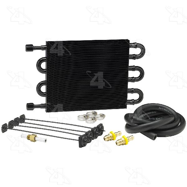
- Transmission Connector Pigtail
(OEM #ACDelco PT2311 (GM 88862230))— This is the most likely failure point according to GM's service bulletin. The female terminals lose tension and fail to make a solid connection. Replacing the entire pigtail is often more reliable than replacing individual terminals.
Trusted brands: ACDelco, Dorman
OEM price range: $50-$120
Aftermarket price range: $20-$60
Related Codes That Often Appear With This One
- U0073 — This is another generic code for 'Controller Area Network (CAN) Bus Communication Off', often set alongside U2100.
- U0100 — Indicates 'Lost Communication With ECM/PCM', which is a specific consequence of the general network failure indicated by U2100.
- U0101 — Indicates 'Lost Communication With TCM', which is a specific consequence of the general network failure indicated by U2100.
- U0121 — Indicates 'Lost Communication With Anti-Lock Brake System (ABS) Control Module', another common result of the network going down.
- P0700 — This code means the Transmission Control Module (TCM) has requested the Check Engine Light be turned on. It is a flag indicating the TCM has stored its own codes, often as a result of the communication loss.
Technical Service Bulletins (TSBs) & Recalls
- PIC4740F (supersedes PIC4740E): Addresses a no-start, no-communication, or various warning lights, pointing to inspecting the transmission X1 connector terminals for a poor fit. This bulletin expands the affected models to include the STS, SRX, CTS, and ATS.
- 08-07-30-021H: A related TSB for other GM trucks and SUVs with 6-speed automatics that details procedures for diagnosing and repairing terminal and connector issues causing GMLAN communication loss, corroborating the repair methodology.
Platform-Specific Known Issues
- Technical Service Bulletin PIC4740F (which supersedes PIC4740E) explicitly calls out unseated or loose-fitting pins in the transmission X1 connector as a primary cause for U2100 and numerous other communication DTCs on the 2006-2011 STS.
Mechanic-Grade Diagnostic Values
- High-Speed GMLAN Bus Resistance — expected: ~60 Ω (Ohms). Failure: A reading of ~120 Ω indicates one of the two terminating resistors is offline. A reading of 0 Ω indicates a short between CAN High and CAN Low wires. An open-loop (infinite) reading indicates a break in the circuit.
- DLC Ground Circuit Resistance — expected: Less than 1.0 Ω (Ohm). Failure: Resistance greater than 1.0 Ω indicates high resistance or an open in the ground circuit for the Data Link Connector, which can disrupt scan tool communication.
- Module Ground Point Resistance (e.g., G201 for BCM) — expected: Less than 3.0 Ω (Ohms). Failure: High resistance on a module's primary ground can cause it to malfunction and disrupt network communication.
- System Voltage (Engine Running) — expected: 13.8V - 14.7V. Failure: Voltage below or above this range indicates a charging system fault (alternator, regulator) which can cause modules to drop off the network.
Scan Tool Commands That Help
- GM Tech2 / GDS2: Module Communication Status — After performing a full vehicle DTC scan, this function is used to see a list of all expected modules on the network and which ones are actively communicating. This is the primary way to identify which module(s) have dropped off the bus, which is essential for isolating the fault.
Wiring & Ground Locations
- X1 — The main 16-pin electrical harness connector on the driver's side of the transmission.. This is the primary failure point identified in GM TSB PIC4740F for U2100. Loose or corroded terminals inside this connector are the most common cause of the network failure.
- G200 — In the passenger compartment, behind the left kick panel.. This is a major interior ground point. A wiring diagram for the 2011 STS shows it serves various modules, and a poor connection here could disrupt network stability.
- G201 — In the passenger compartment, behind the right kick panel.. This is a key ground point for the Instrument Panel Module (IPM) and Body Control Module (BCM) on some GM platforms. A poor connection can cause the BCM, which acts as a network gateway, to malfunction.
- ECM (V8 4.6L) — On the left front frame rail, below the driver's side headlight assembly.. Knowing the location is critical if you need to disconnect the ECM to isolate a network fault or inspect its connectors.
- ECM (V6 3.6L) — On the front of the engine, on the passenger side (right) valve cover.. The location differs from the V8 model. Technicians must know which engine they are working on to find the correct module.
- IPM / IMP — Behind the right side of the dashboard, often accessible by removing the glove box.. The Instrument Panel Module is a key node on the GMLAN. Its connectors or ground (G201) can be a source of faults.
Model Year Variations Within This Range
- 2005-2011: The location of the Engine Control Module (ECM) is different depending on the installed engine. On the 4.6L V8, it is located below the driver's side headlight. On the 3.6L V6, it is located on the passenger side valve cover.
Helpful Videos

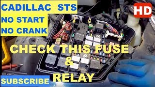
We Have This Part in Stock


The information in this article is provided for general reference and educational purposes only. Vehicle specifications, procedures, and part compatibility can vary by production date, trim level, and region. Always consult your vehicle's factory service manual and verify part numbers before purchasing or performing repairs. Safety-critical components such as airbags, seat belts, and braking systems should be installed by a qualified professional.
- Cadillac STS:
- 🧭 Diagnostic Flowchart
- 🎬 Helpful Videos
- 🛍️ Shop This Part
- What's Unique About the 2006-2011 Cadillac STS
- Symptoms You May Notice
- Most Likely Causes
- Rare But Worth Checking
- Diagnosis Steps
- Parts You'll Likely Need
- Related Codes That Often Appear With This One
- Technical Service Bulletins (TSBs) & Recalls
- Platform-Specific Known Issues
- Mechanic-Grade Diagnostic Values
- Scan Tool Commands That Help
- Wiring & Ground Locations
- Model Year Variations Within This Range
- 🎟️ Get 5% Off