
U2105 on 2013-2015 Cadillac ATS: Lost ECM Communication Causes and Fixes
On a 2013-2015 Cadillac ATS, code U2105 almost always points to a poor connection at the main transmission harness connector (X1 on the driver's side of the transmission), not a failed ECM. The fix is typically inspecting and repairing the connector pins and checking for harness chafing near the bell housing, as outlined in GM Technical Service Bulletin PIC4740E.
- U2105 on your ATS is a network code, not a failed part. Do not replace the expensive ECM or TCM.
- The problem is almost certainly a poor electrical connection at the large X1 connector on the transmission.
- A thorough inspection of the X1 connector pins and the nearby harness for chafing is the first and most important diagnostic step.
- This is a serious code that makes the vehicle unsafe to drive; it requires immediate attention to avoid stalling or unpredictable transmission behavior.
What's Unique About the 2013-2015 Cadillac ATS
The Cadillac ATS, along with other GM vehicles on the Alpha platform like the CTS, is known for network communication problems that originate from a single, well-documented point of failure. General Motors issued Technical Service Bulletin #PIC4740E (and later successors) specifically for the 2013-2015 ATS, directing technicians to a faulty transmission harness connector (X1) as the primary cause for U2105 and a host of other communication codes. The problem is so common that diagnosis should always start at this connector on the driver's side of the transmission before considering any module replacement.
Diagnostic Flowchart
Tap your situation to follow the diagnostic path that matches what you're seeing on this vehicle.
Symptoms You May Notice
- Vehicle will not crank or start. 🎬 Watch: Troubleshooting a common no-start issue on the ATS.
- Transmission shifts very harshly or gets stuck in one gear ('limp mode').
- Check Engine Light (SES light) is on.
- 'Reduced Engine Power' message displayed.
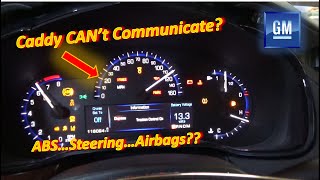
- Multiple warning lights on the dash, such as for ABS and Traction Control.
- Scan tool cannot communicate with the ECM or TCM.
- Door locks may cycle on their own while driving.
- Replacing the Engine Control Module (ECM) without inspecting the X1 connector.
- Replacing the Transmission Control Module (TCM) when the fault is in the external wiring.
Most Likely Causes
- Loose or Unseated Terminals in Transmission Connector X1 🔴 High Probability → Shop Transmission Assembly This is a known issue documented by GM in TSB #PIC4740E. The connector's design or position on the driver's side of the transmission makes it susceptible to vibration and moisture, leading to poor pin contact over time.
How to confirm: Disconnect the large, round, twist-lock X1 connector on the driver's side of the transmission. Carefully inspect for corrosion or damage. Tug gently on each individual wire going into the connector to ensure the terminal is fully seated and locked in place. The TSB warns that a side load on the wire can give a 'false positive' feel, so the test must be done carefully.
Typical fix: Reseat any loose terminals until they click. If terminals are corroded or damaged, they may need to be replaced with new ones. In some cases, the entire connector pigtail may need to be replaced. Applying a small amount of dielectric grease can help prevent future moisture intrusion.
Est. part cost: $5-$70 - Chafed Wiring Harness Near Bell Housing 🟡 Medium Probability TSB #PIC4740E specifically calls out an inspection for the ATS and CTS models. The harness can be improperly routed and rub against a securing bracket on the passenger side of the transmission bell housing, eventually wearing through the insulation and causing a short.
How to confirm: Visually inspect the wiring harness where it passes the securing bracket on the passenger side of the engine/transmission junction. Look for any signs of rubbing, exposed copper wire, or damage to the loom. The TSB states the harness should hang *below* the bracket.
Typical fix: Repair the damaged wires using solder and heat shrink tubing. Re-route the harness to prevent it from contacting the bracket again, ensuring it hangs below the bracket as intended.
Est. part cost: $0-$20
Rare But Worth Checking
- Failed Engine Control Module (ECM): → Shop Engine Control Module (ECM) This is very rare. Before condemning the ECM, all wiring and connector issues must be exhaustively ruled out. An ECM failure is unlikely to be intermittent and would typically result in a permanent no-communication state.
- Failed Transmission Control Module (TCM): → Shop Transmission Assembly Similar to the ECM, a TCM failure is uncommon. Since the problematic X1 connector is the primary interface to the TCM, a fault there is far more probable.
Diagnosis Steps
- Check for other stored Diagnostic Trouble Codes (DTCs). A long list of U-codes strongly suggests a network wiring issue, not a single failed module.
- Gain access to the transmission, which may require a vehicle lift. The X1 connector is a large, round, twist-lock connector located on the driver's side of the transmission housing.
- Disconnect the X1 connector. Visually inspect both the male and female sides for any green or white corrosion, bent pins, or signs of water intrusion.
- Perform a 'tug test' on every wire entering the back of the connector, as described in TSB #PIC4740E. Pull gently to ensure each terminal is securely locked in place. A loose pin is the most common fault.
- Specifically for the ATS, locate and inspect the wiring harness near the securing bracket on the passenger side of the bell housing for any signs of chafing or damage. Ensure the harness is routed below the bracket.
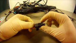
- If a loose terminal is found, use a proper terminal tool to remove and reseat it. 🎬 See how to properly de-pin and re-pin GM connectors. If damaged, replace the terminal.
- If chafing is found, repair the affected wires with solder and heat-shrink tubing, then secure the harness away from the sharp edge.
- If no wiring or connector faults are found, a professional technician would then use a multimeter to check for proper power, ground, and CAN bus resistance (typically 60 ohms between Pin 6 and Pin 14 of the DLC with the battery disconnected).
- Clear all DTCs and perform a test drive to see if the codes return.
Parts You'll Likely Need
- Connector Terminals / Pins — The small metal terminals inside the plastic X1 connector are the most common point of failure, becoming loose or corroded.
Trusted brands: ACDelco
OEM price range: $5-$15
Aftermarket price range: $2-$10 - Transmission Harness Connector Pigtail
(OEM #ACDelco PT2711 (GM 13580975))— If the main connector housing is damaged or multiple terminals are corroded, replacing the entire connector pigtail is often the most reliable repair. This part number is a widely used GM connector pigtail that may be applicable.
Trusted brands: ACDelco, Dorman
OEM price range: $40-$70
Aftermarket price range: $25-$50
Related Codes That Often Appear With This One
- U0100 — Lost Communication With ECM/PCM. This is a similar code set by a different module, pointing to the same network failure.
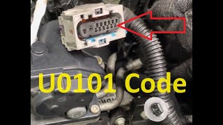
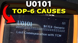
- U0101 — Lost Communication With TCM. This code is frequently set with U2105 because the problematic X1 connector is the main electrical interface for the transmission.
- P0700 — Transmission Control Module (TCM) Requested MIL Illumination. This indicates the TCM has detected a serious fault (like a loss of communication) and has asked the ECM to turn on the Check Engine Light.
- U2100 — Controller Area Network (CAN) Bus Communication. This is a general network code indicating a disruption on the communication bus, consistent with the root cause.
- U2106 — Lost Communication With Transmission Control Module (TCM). This is another code pointing directly to a communication loss with the TCM, often caused by the X1 connector issue.
Technical Service Bulletins (TSBs) & Recalls
- PIC4740E: Addresses multiple communication DTCs, including U2105, and symptoms like no-crank or hard shifting. It points to loose terminals in the transmission X1 connector and potential harness chafing on the ATS as the cause. This TSB has been superseded by newer versions (like PIC4740F) but the diagnostic advice remains the same.
Platform-Specific Known Issues
- Loose Terminals in Transmission Connector X1: → Shop Transmission Assembly A known issue documented in GM TSB #PIC4740E involves loose terminals in the transmission X1 connector causing a loss of communication. The connector is located on the driver's side of the transmission.
- Harness Chafing at Bell Housing Bracket: The same TSB also highlights a potential for the wiring harness to chafe on a securing bracket near the passenger side of the bell housing on the Cadillac ATS, leading to short circuits. The harness should be routed below this bracket.
Mechanic-Grade Diagnostic Values
- High-Speed GMLAN Bus Resistance — expected: 60 Ohms. Failure: A reading of 120 Ohms indicates a missing terminating resistor or an open circuit. A reading near 0 Ohms indicates a short between the CAN High and CAN Low wires.
- High-Speed GMLAN Bus Voltage (Recessive State) — expected: ~2.5V on both CAN High and CAN Low. Failure: Significant deviation from 2.5V on either line when the bus is at rest (Key On, Engine Off, no active communication) points to a short, open, or faulty module transceiver.
- High-Speed GMLAN Bus Voltage (Dominant State) — expected: CAN High: ~3.5V, CAN Low: ~1.5V. Failure: Inability for the lines to be driven to these voltages during communication (best viewed on an oscilloscope) indicates a network problem.
Hidden / Shadow Codes Worth Checking
- U2105 00: On GM vehicles, a two-digit 'symptom byte' is often appended to the DTC. For this code, it is commonly U2105 00, where '00' means 'No Additional Information'. This indicates a general loss of communication without pointing to a more specific failure type like 'invalid data'. (see via A professional scan tool like a GM GDS2 or Tech2 will display the full DTC with the symptom byte.)
Wiring & Ground Locations
- DLC (OBD-II Port) Pins 6 & 14 — Under the driver's side dashboard.. These are the direct access points for testing the High-Speed GMLAN bus. Pin 6 is CAN High and Pin 14 is CAN Low. All network-level voltage and resistance tests are performed here.
- G103 — Located at the left rear of the engine compartment on the cowl, above the brake booster.. This is a primary ground point for the Body Control Module (BCM) and the Data Link Connector (DLC). A poor connection here can cause strange electrical issues and prevent a scan tool from communicating properly, complicating diagnosis.
- G104 — On the front of the right cylinder head (3.6L) or the lower rear of the cylinder head (2.0T/2.5L).. This serves as a ground for several critical components, including the Electronic Brake Control Module (EBCM). Since the EBCM is a key module on the high-speed CAN bus, a bad ground here can disrupt the entire network and set communication codes like U2105.
OEM Part Supersession History
PIC4740D→PIC4740E— To update the list of affected models and model year VIN breaks. Later versions (e.g., PIC4740F) may also exist.
Heads up: The core diagnostic advice regarding the X1 connector and harness chafing remains consistent across all versions of this TSB.
Model Year Variations Within This Range
- 2013-2014: While the root cause documented in TSB PIC4740E is consistent, minor differences exist in component locations between model years. For example, the specific location of engine ground G106 differs slightly between 2013 and 2014 wiring diagrams. These minor variations do not change the primary diagnostic path for U2105.
Helpful Videos

We Have This Part in Stock


The information in this article is provided for general reference and educational purposes only. Vehicle specifications, procedures, and part compatibility can vary by production date, trim level, and region. Always consult your vehicle's factory service manual and verify part numbers before purchasing or performing repairs. Safety-critical components such as airbags, seat belts, and braking systems should be installed by a qualified professional.
- Cadillac ATS:
- 🧭 Diagnostic Flowchart
- 🎬 Helpful Videos
- 🛍️ Shop This Part
- What's Unique About the 2013-2015 Cadillac ATS
- Symptoms You May Notice
- Most Likely Causes
- Rare But Worth Checking
- Diagnosis Steps
- Parts You'll Likely Need
- Related Codes That Often Appear With This One
- Technical Service Bulletins (TSBs) & Recalls
- Platform-Specific Known Issues
- Mechanic-Grade Diagnostic Values
- Hidden / Shadow Codes Worth Checking
- Wiring & Ground Locations
- OEM Part Supersession History
- Model Year Variations Within This Range
- 🎟️ Get 5% Off