
U2105 on 2006-2011 Cadillac STS: Lost Communication with ECM Causes and Fixes
This code on a 2006-2011 Cadillac STS most often points to a poor connection at the main transmission harness connector (X1). Inspecting and securing the pins in this connector, as detailed in GM Technical Service Bulletin PIC4740F, is the most common fix.
- U2105 on a 2006-2011 STS means the network has lost communication with the Engine Control Module (ECM).
- Before suspecting a bad ECM, you MUST inspect the transmission harness connector (X1) for loose pins, as this is the most common cause documented in a GM service bulletin.
- Symptoms are severe and can include a no-start condition, reduced power, and harsh shifting, making the vehicle unsafe to drive.
- This is often a wiring issue, not a module failure. A thorough inspection of the connector and harness can prevent the unnecessary expense of replacing the ECM or TCM.
What's Unique About the 2006-2011 Cadillac STS
The Cadillac STS from this era, along with several other GM platform mates, is specifically known for communication issues stemming from a single point of failure: the transmission harness connector, designated X1. General Motors issued a Technical Service Bulletin (PIC4740F, superseding earlier versions) that directly links U2105 and a host of other communication codes to poorly seated or loose terminals within this specific connector. The TSB warns that when performing the 'tug test' on the wires, a side load may cause a 'false positive lock,' making a loose pin feel secure when it is not. While other vehicles might have this code due to module failure, on the STS, this physical wiring connection is the primary and well-documented suspect.
Diagnostic Flowchart
Tap your situation to follow the diagnostic path that matches what you're seeing on this vehicle.
Symptoms You May Notice
- Check Engine Light (SES light) is on
- Vehicle will not crank or start
- Engine running in Reduced Power mode
- Harsh or erratic transmission shifting
- Multiple warning lights on the dashboard (e.g., StabiliTrak, ABS)
- Scan tool cannot communicate with the ECM or TCM
- Door locks may cycle while driving
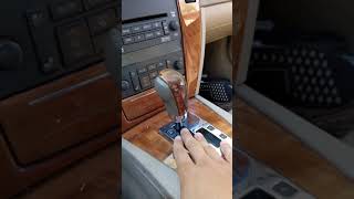
- Instrument cluster goes blank when attempting to start 🎬 Watch: Troubleshooting a 2006 STS with a no-start condition.
- Replacing the Engine Control Module (ECM) or Transmission Control Module (TCM) without first thoroughly inspecting the transmission X1 connector and related wiring harness. The TSB clearly indicates the wiring is the most likely culprit.
Most Likely Causes
- Poorly Seated Terminals in Transmission Connector X1 🔴 High Probability → Shop Transmission Assembly This is a well-documented issue covered by GM Technical Service Bulletin PIC4740F. The design or assembly of the connector can lead to pins backing out over time, causing intermittent loss of connection.
How to confirm: Disconnect the X1 connector at the transmission (located on the driver's side of the transmission). Gently tug on each individual wire. A properly seated terminal will not move. The TSB specifically warns that 'a side load on the wires may cause a false positive lock,' so be thorough. A loose wire confirms the fault.
Typical fix: Reseat the loose terminal(s) securely into the connector until it clicks. If the terminal or connector housing 🎬 See how to properly remove and reseat GM transmission pins. is damaged, it will need to be replaced. Applying a small amount of dielectric grease can help prevent future moisture intrusion.
Est. part cost: $0-$50 - Damaged Wiring Harness 🟡 Medium Probability Wiring harnesses can chafe against engine or transmission components, leading to shorts or open circuits in the CAN bus lines. The TSB mentions inspecting the harness near the securing bracket on the passenger side of the bell housing, particularly on CTS and ATS models, but it's a known weak point for the general architecture.
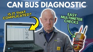
How to confirm: Visually inspect the wiring harness running to the transmission and between the major control modules (ECM, TCM, BCM) for any signs of chafing, melting, or corrosion. A multimeter can be used to check for continuity and resistance on the CAN bus wires (typically looking for 60 ohms between CAN High and CAN Low 🎬 Watch this guide to learn how to troubleshoot CAN BUS faults. with the battery disconnected).
Typical fix: Repair the damaged section of wire. This involves cutting out the bad section, splicing in a new piece of wire of the same gauge, and protecting the repair with solder and heat-shrink tubing.
Est. part cost: $5-$25 - Faulty Control Module (ECM or TCM) ⚪ Low Probability
How to confirm: This should only be considered after all wiring and connector issues have been ruled out per TSB PIC4740F. A professional will need to use an advanced scan tool to attempt to communicate directly with the module and check its power and ground circuits before condemning the module.
Typical fix: Replace the failed module. The new module will require programming to the vehicle's VIN with a specialized tool.
Est. part cost: $200-$800
Rare But Worth Checking
- Poor Module Power or Ground: A corroded or loose ground connection for the ECM or TCM can cause intermittent communication failures that mimic a bad module. Always check main grounds before replacing expensive components.
Diagnosis Steps
- Scan all vehicle modules for stored trouble codes. Note all communication ('U') codes present.
- Check for Technical Service Bulletins (TSBs) related to your vehicle and codes. Specifically, reference GM TSB #PIC4740F for the U2105 code.
- Locate the main transmission electrical connector (X1), which is a large, round, twist-lock connector on the driver's side of the transmission.
- Disconnect the connector. Carefully inspect the connector terminals on both the harness side and the transmission side for corrosion, moisture, or damage.
- Gently tug each wire leading into the back of the harness-side connector. Identify any wires that feel loose or pull out. Be aware of the TSB warning that a 'side load on the wires may cause a false positive lock.'
- Repair any loose terminals by pushing them back into the connector until they click and are secure. Use a proper terminal repair tool if necessary. Replace any damaged terminals or the connector housing if needed.
- If the connector is secure, visually inspect the wiring harness for chafing or damage, especially where it runs near the engine bell housing.
- If no wiring faults are found, use a multimeter to check the resistance of the CAN bus circuit. With the battery disconnected, measure between pins 6 and 14 of the OBD-II port. A reading of approximately 60 ohms is expected. A reading of 120 ohms or an open circuit indicates a break in the wiring or a faulty module.
- As a final step, verify that the ECM and TCM have proper power and ground connections before considering module replacement.
Parts You'll Likely Need
- Connector Terminals / Pins
(OEM #Varies, dealer-sourced)— The most common cause of this code is a loose or backed-out terminal in the transmission connector, as per TSB PIC4740F. These are often not sold as individual aftermarket parts and may require a trip to a GM dealer's parts counter.
Trusted brands: ACDelco, GM Genuine
OEM price range: $5-$15 per terminal
Aftermarket price range: $2-$10 per terminal - Transmission Harness Connector (Pigtail)
(OEM #Varies, e.g., 24232175, 15131300)— If the connector housing itself is cracked, melted, or too damaged to hold the terminals securely, a replacement pigtail will be needed. This part contains the connector and a short length of wires to be spliced into the main harness.
Trusted brands: ACDelco, Dorman, Standard Motor Products
OEM price range: $40-$75
Aftermarket price range: $25-$50
Related Codes That Often Appear With This One
- U0073 — A general CAN Bus Communication fault, often set alongside more specific 'Lost Communication' codes.
- U0100 — This is a generic code for 'Lost Communication with ECM/PCM', which is a broader version of U2105.
- U0101 — Indicates 'Lost Communication with TCM'. Since the problematic X1 connector is on the transmission, it's common for communication to be lost with both the ECM and TCM.
- U2100 — Another general CAN Bus Communication code that points to a network-wide problem rather than a single module failure.
- U2106 — Indicates 'Lost Communication with Transmission Control Module (TCM)', often set with U2105 due to the location of the fault in the transmission connector.
- P0700 — This code means the Transmission Control Module (TCM) has requested the Check Engine Light to be turned on. It's a flag indicating a fault is stored in the TCM, often a communication code like U2105 or U2106.
Technical Service Bulletins (TSBs) & Recalls
- PIC4740F: Addresses multiple communication DTCs (including U2105) and symptoms like no-crank or hard shifting, pointing to loose terminals in the transmission X1 connector as the primary cause. It applies to the STS and other GM models like the SRX and CTS.
Platform-Specific Known Issues
- GM Technical Service Bulletin PIC4740F (and its previous versions) specifically calls out unseated pins in the transmission connector X1 as the cause for a wide range of communication DTCs, including U2105, on the 2006-2011 Cadillac STS.
- Owner Experience: Incorrect Workarounds: Some owners, faced with a no-crank situation from this code, have resorted to installing a jumper wire and a separate button to directly energize the starter relay, bypassing the vehicle's security and control modules. One owner who did this noted that while the car would start, the transmission continued to shift erratically because the underlying communication problem between the ECM and TCM was never resolved. This highlights the importance of fixing the root cause rather than just treating the 'no-start' symptom.
Mechanic-Grade Diagnostic Values
- High-Speed CAN Bus Network Resistance — expected: Approximately 60 Ω (Ohms). Failure: A reading of ~120 Ω indicates an open circuit or missing terminating resistor. A reading near 0 Ω indicates a short between the CAN High and CAN Low wires.
- CAN High Voltage (Active Bus) — expected: ~2.6V DC (average). Failure: Significant deviation from 2.6V can indicate a bus problem. An oscilloscope is required for definitive analysis, but a multimeter provides a basic health check.
- CAN Low Voltage (Active Bus) — expected: ~2.4V DC (average). Failure: Significant deviation from 2.4V can indicate a bus problem. An oscilloscope is required for definitive analysis.
Scan Tool Commands That Help
- GM Tech 2 with CANdi Module or GDS2: Vehicle DTC Information / Module Diagnostics — Use this function to poll all modules on the network. If the ECM or TCM does not respond or shows a 'No Communication' status, it confirms the fault. The Tech 2 requires a CANdi module for 2006+ CAN vehicles.
- GDS2: Data Bus Diagnostic Tool — This specialized tool within GDS2 can perform a network-wide check, listing all modules that are actively communicating. By comparing the list of communicating modules to the vehicle's schematic, a technician can quickly identify which modules are offline and where the communication break likely is.
Wiring & Ground Locations
- ECM (4.6L V8) — On the left (driver's side) front frame rail, located below the headlamp assembly. May require removing the engine splash shield for access.. The ECM is one of the two primary modules in a U2105 fault. Its physical location is needed to check its connectors and ground integrity.
- ECM (3.6L V6) — On the front of the engine, mounted on the right (passenger side) valve cover.. The ECM's location varies by engine. Technicians must know where to find it to check its connections and ground.
- TCM (External) — For models with an external TCM, it is often located under the left side of the instrument panel.. This is a potential location for the other module involved in the U2105 code. Verifying its connections is a key diagnostic step if it's not internal to the transmission.
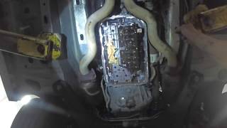
- TEHCM (Internal TCM) — For models equipped with the 6L45, 6L50, or 6L80 transmission, the TCM is integrated into the valve body inside the transmission oil pan. This unit is called a TEHCM.. If the vehicle has a TEHCM, the main X1 connector on the outside of the transmission case is the primary point of failure, not a separate module under the dash.
- G100 / G106 — On the rear side of the right (passenger side) cylinder head.. A wiring diagram for the 2006 STS indicates this is a ground point for both the ECM and TCM, making its integrity critical for network communication.
- G102 — Located at the lower right rear of the engine, near the power steering rack. Another source says lower left front of the engine block. Location may vary by engine/year.. This is a primary engine block ground. A poor connection here can cause voltage potential differences between modules, disrupting CAN communication.
- G101 — Near the left front strut tower, at the bottom of the inside fender well. Another source indicates it's at the lower block and grounds the ECM/TCM.. This is a key chassis ground point. Since the battery is in the rear, clean chassis and engine-to-chassis grounds are essential.
Real Owner Repair Stories
- YouTube user 'Marcus Dickinson' (2006 Cadillac STS) — No crank, no start condition. Dash would cut off when trying to start.
❌ Tried (didn't work) Sending it to a shop without trying simple fixes.
✅ What actually fixed it The owner removed the four main relays (related to ignition, crank, and start) from the underhood fuse box and found corrosion on the relay pins and in the fuse box sockets. Cleaning the corrosion from the relays and spraying electrical contact cleaner into the sockets resolved the no-start issue. - YouTube user 'ScannerDanner' (Cadillac with a rear-mounted battery (similar architecture to STS)) — No crank, bizarre electrical behavior, low voltage readings at the underhood fuse box despite a fully charged battery.
❌ Tried (didn't work) Initial diagnosis pointed towards a bad positive battery cable or fuse box due to the voltage drop.
✅ What actually fixed it The main engine block ground strap, which provides the ground path for the starter and engine electronics back to the chassis, was completely broken off. This created a floating ground, causing extreme voltage drops under load and preventing the car from starting. Replacing the ground strap fixed all issues.
OEM Part Supersession History
24259639, 24257213, etc.→24275873, 24275874— Updates and revisions to the internal TEHCM (Transmission Electro-Hydraulic Control Module) for 6L-series transmissions.
Heads up: These parts are for the internal transmission module (TEHCM) and are not the same as the external X1 connector. The TEHCM must be programmed to the vehicle after installation.
Model Year Variations Within This Range
- 2006-2011 (Varies by transmission option): The location of the Transmission Control Module (TCM) is a significant variation. Some configurations use an external TCM, often found under the instrument panel. However, many STS models in this range, particularly those with 6-speed automatics like the 6L50, use an integrated Transmission Electro-Hydraulic Control Module (TEHCM) located inside the transmission on the valve body. For TEHCM-equipped vehicles, the diagnosis of U2105 focuses almost exclusively on the external X1 connector and wiring, as there is no separate external TCM to inspect.
Helpful Videos

We Have This Part in Stock


The information in this article is provided for general reference and educational purposes only. Vehicle specifications, procedures, and part compatibility can vary by production date, trim level, and region. Always consult your vehicle's factory service manual and verify part numbers before purchasing or performing repairs. Safety-critical components such as airbags, seat belts, and braking systems should be installed by a qualified professional.
- Cadillac STS:
- 🧭 Diagnostic Flowchart
- 🎬 Helpful Videos
- 🛍️ Shop This Part
- What's Unique About the 2006-2011 Cadillac STS
- Symptoms You May Notice
- Most Likely Causes
- Rare But Worth Checking
- Diagnosis Steps
- Parts You'll Likely Need
- Related Codes That Often Appear With This One
- Technical Service Bulletins (TSBs) & Recalls
- Platform-Specific Known Issues
- Mechanic-Grade Diagnostic Values
- Scan Tool Commands That Help
- Wiring & Ground Locations
- Real Owner Repair Stories
- OEM Part Supersession History
- Model Year Variations Within This Range
- 🎟️ Get 5% Off