
U2106 on 2013-2015 Cadillac ATS: Causes and Fixes for Lost Communication with TCM
This code almost always points to a poor electrical connection at the main transmission wiring harness connector (X1). As per GM Technical Service Bulletin PIC4740E (and its successor, PIC4740F), inspecting, cleaning, and ensuring all pins are fully seated in this connector is the most common and cost-effective fix, often resolving the issue without replacing any parts.
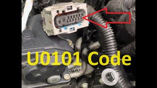
- U2106 on a 2013-2015 ATS is a network code indicating a loss of communication with the Transmission Control Module (TCM).
- Before suspecting any expensive part failures, your first and most important step is to inspect the transmission's main X1 electrical connector for loose or corroded pins, as per GM TSB PIC4740E.
- Also inspect the wiring harness for chafing near the bell housing bracket, a specific weak point noted for the ATS.
- Symptoms are often severe, including harsh shifting, a no-start condition, and multiple dashboard warning lights, making the vehicle unsafe to drive.
- Do not immediately replace the TCM; the problem is far more likely to be a simple wiring or connector issue that is inexpensive to fix.
What's Unique About the 2013-2015 Cadillac ATS
For this specific generation of the Cadillac ATS, General Motors issued Technical Service Bulletin #PIC4740E and its successor PIC4740F, which directly addresses code U2106 along with a host of other communication codes. The bulletin identifies the primary cause as poorly seated or corroded terminal pins within the main transmission harness connector (X1). The TSB specifically warns that 'A side load on the wires may cause a false positive lock,' meaning a pin can feel secure when it is not, making a physical tug test on each wire essential. This makes the diagnostic process more straightforward than a generic communication code, as it points technicians to a well-documented and highly probable failure point before they consider more expensive repairs like module replacement.
Diagnostic Flowchart
Tap your situation to follow the diagnostic path that matches what you're seeing on this vehicle.
Symptoms You May Notice
- Check Engine Light (SES light) is on
- Transmission shifts harshly or erratically
- Vehicle enters 'Reduced Power' mode
- Vehicle may not crank or start
- Multiple warning lights on the dashboard (e.g., ABS, Traction Control)
- Door locks cycle erratically while driving
- Scan tool cannot communicate with the TCM or ECM
- Gauges may fluctuate or drop out intermittently
- Replacing the Transmission Control Module (TCM) before thoroughly inspecting the X1 connector and wiring harness. The TSB clearly indicates the wiring/connector is the most frequent cause.
Most Likely Causes
- Loose or Unseated Pins in Transmission Connector (X1) 🔴 High Probability → Shop Transmission Assembly This is a well-documented failure point specified directly in GM TSB #PIC4740E/F. The bulletin notes that terminals can have a 'false lock' where they seem connected but are not, leading to intermittent communication loss due to vibration and environmental exposure.
How to confirm: Disconnect the X1 connector on the transmission. Visually inspect for corrosion, moisture, or backed-out pins. Gently tug on each individual wire to ensure it is fully seated and locked in place, as recommended by the TSB.
Typical fix: Reseat any loose terminals until they click. Clean the connector pins with electrical contact cleaner and apply dielectric grease before reconnecting. If terminals are damaged, the connector pigtail may need to be replaced.
Est. part cost: $0-$70 - Chafed or Damaged Wiring Harness 🟡 Medium Probability TSB #PIC4740F specifically calls out an issue for the ATS where the wiring harness can chafe against its securing bracket near the transmission bell housing. A CadillacForums user with a similar platform (CTS) reported finding the chafed harness behind the passenger side front wheel well liner, which shorted the CAN bus wires.
How to confirm: Visually inspect the wiring harness, especially near the securing bracket on the passenger side where the transmission bell housing attaches to the engine block, for signs of rubbing, melting, or breaks. It may be necessary to remove the wheel well liner for a better view.
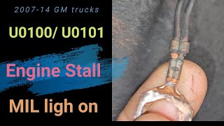
Typical fix: Repair the damaged section of wire by soldering or using quality butt connectors with heat shrink tubing. 🎬 See this guide on how to repair a damaged wiring harness Reroute or secure the harness with anti-abrasion tape and zip ties to prevent future damage.
Est. part cost: $5-$20 - Loss of Power or Ground to the TCM ⚪ Low Probability While less common than the connector issue, corroded ground points or fuse block terminals can cause a module to drop offline. A Reddit user noted that poor grounds on the engine block and head are a known source of electrical issues on the ATS.
How to confirm: Using a multimeter and wiring diagram, check for proper battery voltage and a solid ground connection at the TCM connector. Check all related fuses (often labeled TCM, ECM, etc.) in the fuse box.
Typical fix: Replace any blown fuses. Clean corroded ground points or fuse block terminals. Repair any broken power or ground wires.
Est. part cost: $1-$25
Rare But Worth Checking
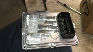
- Failed Transmission Control Module (TCM): → Shop Transmission Assembly This is rare and should only be considered after all wiring and connector issues have been ruled out. The TCM is often located inside the transmission oil pan (as a TEHCM) and replacement is labor-intensive and requires programming by a dealer or qualified shop. 🎬 Watch: How to remove and install a Cadillac ATS TCM
- Low Battery Voltage: Control modules are sensitive to system voltage. A weak, old, or failing battery can cause a variety of unpredictable communication errors, including U2106, especially during cranking.
Diagnosis Steps
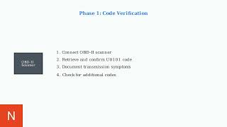
- Perform a full vehicle scan to identify all stored DTCs. Note any other 'U' codes, as well as P0700. A long list of communication codes points towards the TSB-documented issue.
- Check battery voltage. Ensure the battery is fully charged (above 12.4V) and healthy, as low voltage can cause spurious communication codes.
- Locate the main transmission wiring harness connector (X1) on the side of the transmission.
- Disconnect the X1 connector. Inspect the pins and terminals for any signs of corrosion, moisture, or physical damage.
- As per TSB PIC4740F, carefully and gently tug on each individual wire going into the back of the connector. Any wire that feels loose or pulls out is not properly seated.
- If a terminal is loose, reseat it firmly until it clicks into place. Clean the connector with electrical contact cleaner and apply a small amount of dielectric grease to the seal before reconnecting.
- Inspect the wiring harness for chafing, particularly at the securing bracket on the passenger side of the transmission bell housing, as noted in the TSB for the ATS. Also check behind the passenger front wheel well liner.
- If the connector and harness appear intact, use a multimeter to check for proper power and ground at the TCM connector according to the vehicle's wiring diagram.
- If all wiring, power, and grounds are good, the final step is to suspect a faulty TCM. This requires a professional-level scan tool to confirm.
Parts You'll Likely Need
- Transmission Wire Harness Connector Pigtail
(OEM #ACDelco PT2712 (GM 13580113))— If the original X1 connector or its terminals are damaged or corroded beyond cleaning, a new pigtail must be spliced into the harness. This 14-way connector is for the 6L45/6L50 transmission. [NOTE: See Pass 3 Corrections. This part number may be incorrect.]
Trusted brands: ACDelco, Dorman
OEM price range: $40-$80
Aftermarket price range: $25-$50 - Electrical Contact Cleaner — Used for cleaning corrosion and dirt from the pins of the X1 connector to ensure a good electrical connection.
Trusted brands: CRC, WD-40 Specialist
Aftermarket price range: $5-$15
Related Codes That Often Appear With This One
- P0700 — This is a generic code that means the TCM has stored a fault and requested the check engine light. It's a flag that points to a transmission-related issue and is explicitly listed in TSB PIC4740F.
- U0073 — This code indicates a general Controller Area Network (CAN) Bus communication error. It often appears with U2106 when the network is disrupted.
- U0100 — Indicates 'Lost Communication With ECM/PCM'. This can be set along with U2106 if the network fault is severe enough to affect multiple critical modules.
- U0121 — Indicates 'Lost Communication With Anti-Lock Brake System (ABS) Control Module'. This is another code listed in the TSB that points to a widespread network communication problem originating from the same root cause.
- U0140 — Indicates 'Lost Communication With Body Control Module'. Also listed in the TSB, its presence further confirms a significant network issue.
Technical Service Bulletins (TSBs) & Recalls
- PIC4740F: (Supersedes PIC4740E) Addresses no crank, multiple warning lights, and harsh shifting due to unseated pins in the transmission connector or a chafed harness. It lists U2106 as one of the primary codes associated with this condition and expands the list of affected vehicles.
Platform-Specific Known Issues
- Per TSB PIC4740F, the 2013-2015 ATS is prone to unseated pins in the transmission X1 connector, which can create a 'false lock' and lead to intermittent communication loss.
- The same TSB also highlights a specific inspection point for the ATS: checking for harness chafing at the securing bracket on the passenger side of the transmission bell housing.
Mechanic-Grade Diagnostic Values
- High-Speed GMLAN Bus Resistance — expected: ~60 Ω. Failure: A reading of ~120 Ω indicates an open circuit or that a terminating module (like the TCM) is disconnected. A reading near 0 Ω indicates a short between the CAN High and CAN Low wires.
Scan Tool Commands That Help
- GDS2 (GM Global Diagnostic System 2): Vehicle DTC Information — This is the initial step to perform a vehicle-wide scan, which is critical for a network code like U2106. Seeing a large number of 'U' codes across multiple modules points to a network-wide fault, as described in TSB PIC4740F.
- GDS2 (GM Global Diagnostic System 2): Clear All DTCs — Used after the physical repair (e.g., reseating the X1 connector) has been completed to clear the fault codes from all modules and turn off the check engine light.
- GDS2 (GM Global Diagnostic System 2): Module Diagnostics > TCM > Data Display — If communication with the TCM is intermittent, this function can be used to view live data from the module when it is online. This can help confirm if the module itself is functioning correctly when it does have power and communication.
Wiring & Ground Locations
- X1 Connector (TCM) — The main electrical harness connector located on the side of the transmission assembly.. This is the primary failure point identified in TSB PIC4740F. The CAN bus wires that carry communication to and from the TCM pass through this connector.
- TCM CAN Bus Pins (at X1) — Within the main transmission X1 connector. On a 2015 ATS, the pins are Pin 14 (High Speed GMLAN Serial Data Bus +) and Pin 15 (High Speed GMLAN Serial Data Bus -).. These are the specific pins for the communication network. A poor connection or damage to these two pins is the direct cause of the U2106 code.
- G104 (Engine Ground) — An engine-to-chassis ground. For 2013 ATS models with 4-cylinder engines, its location changed mid-year: early production models have it at the front of the engine, while models made after mid-December 2012 have it at the rear of the engine. For non-3.6L engines, it's generally found on the lower rear of the cylinder head.. A poor engine ground can cause fluctuating voltages and disrupt module communication. TSB PI1097A highlights this as a source of intermittent electrical issues on the ATS.
- Harness Securing Bracket — On the passenger side of the vehicle, where the transmission bell housing attaches to the engine block.. TSB PIC4740F specifically calls out this location on the ATS as a potential chafe point where the wiring harness can rub through, causing shorts in the CAN bus wiring.
Model Year Variations Within This Range
- 2013: The location of the G104 engine ground on 4-cylinder (LCV, LTG) automatic models changed. Start-of-production models through mid-December 2012 have the ground at the front of the engine. Later 2013 models have it at the rear of the engine.
Helpful Videos
We Have This Part in Stock


The information in this article is provided for general reference and educational purposes only. Vehicle specifications, procedures, and part compatibility can vary by production date, trim level, and region. Always consult your vehicle's factory service manual and verify part numbers before purchasing or performing repairs. Safety-critical components such as airbags, seat belts, and braking systems should be installed by a qualified professional.
- Cadillac ATS:
- 🧭 Diagnostic Flowchart
- 🎬 Helpful Videos
- 🛍️ Shop This Part
- What's Unique About the 2013-2015 Cadillac ATS
- Symptoms You May Notice
- Most Likely Causes
- Rare But Worth Checking
- Diagnosis Steps
- Parts You'll Likely Need
- Related Codes That Often Appear With This One
- Technical Service Bulletins (TSBs) & Recalls
- Platform-Specific Known Issues
- Mechanic-Grade Diagnostic Values
- Scan Tool Commands That Help
- Wiring & Ground Locations
- Model Year Variations Within This Range
- 🎟️ Get 5% Off