
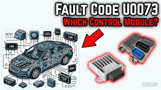
U0073 on 2007-2014 Chevrolet Corvette: Control Module Communication Bus 'A' Off Fixes
U0073 on a 2007-2014 Corvette indicates a total loss of communication on the vehicle's main data network (CAN bus). This is often caused by a wiring issue, such as a backed-out terminal in the transmission harness connector, a poor ground, or a faulty module like the EBCM bringing the network down. Diagnosis is complex, but the fix is often a wiring repair rather than expensive module replacement.
- U0073 is a serious network failure code, not a simple part failure. Do not immediately replace expensive modules.
- The most likely cause on a C6 Corvette is a wiring or connection issue, specifically the 16-pin connector at the automatic transmission, as per a GM TSB.
- Always start diagnosis by checking the battery and all major ground connections. A weak electrical foundation is a common source of communication faults.
- This code almost always appears with other 'U' codes (like U0100, U0101, U0121) and P0700, confirming a system-wide communication breakdown.
- Due to the complexity, professional diagnosis with a scan tool that can read network status is strongly recommended to avoid costly and ineffective parts replacement.
What's Unique About the 2007-2014 Chevrolet CORVETTE
The 2007-2014 Corvette range spans two generations, the C6 (2005-2013) and the first year of the C7 (2014). Both are electronically complex, making network diagnostics challenging. A key GM Technical Service Bulletin (TSB #08-07-30-021H) specifically points to communication issues on these platforms, often stemming from seemingly minor wiring faults that cause a cascade of error codes. Forum discussions among C6 owners frequently highlight frustrating, hard-to-diagnose electrical gremlins related to the CAN bus, sometimes leading to repeatedly replacing parts without solving the root cause. Common failure points include the 16-way transmission connector, grounds near the battery, and the Electronic Brake Control Module (EBCM) itself.
Diagnostic Flowchart
Tap your situation to follow the diagnostic path that matches what you're seeing on this vehicle.
Generation note: This range covers the latter part of the C6 generation (2007-2013) and the first model year of the C7 (2014). While the underlying GMLAN architecture is similar, specific module locations and wiring harnesses differ. The provided TSB #08-07-30-021H applies up to the 2014 model year and highlights a common failure pattern of backed-out terminals in harness connectors that is relevant to the entire C6 generation and other GM vehicles of the era. The C6 utilizes a high-speed GMLAN bus for critical systems and a slower, single-wire Class 2 serial data bus for less critical modules like infotainment and door controls.
Symptoms You May Notice
- Transmission may not shift or gets stuck in one gear (limp mode).
- Multiple warning lights on the instrument panel, such as 'Service Active Handling', 'Service Traction Control', 'Service Rear Axle'.
- Instrument panel gauges fluctuating or dropping to zero.
- Engine may not crank or start intermittently.
- Intermittent cycling of door locks or chime operation.
- Check Engine Light is on.
- Loss of power steering or other features
- Rough idle or engine will not rev.
- DIC (Driver Information Center) displays multiple service messages.
- Replacing the Transmission Control Module (TCM) or Engine Control Module (ECM) without first thoroughly inspecting the wiring harness, connectors, and grounds. Many owners have replaced expensive modules only to have the problem return because the root cause was a simple connection issue.
Most Likely Causes
- Backed-out or Corroded Terminal in Transmission Harness Connector 🔴 High Probability → Shop Transmission Assembly A specific GM TSB (#08-07-30-021H) identifies this as a known issue. The 16-way electrical connector to the automatic transmission is susceptible to terminals backing out or getting contaminated with fluid, breaking the GMLAN serial data bus circuit (typically Tan and Tan/Black wires).
How to confirm: Visually inspect the 16-way connector at the transmission for any terminals that are not fully seated. Check for signs of transmission fluid contamination inside the connector. Ensure the Terminal Position Assurance (TPA) lock is fully seated.
Typical fix: Reseat the backed-out terminal and secure it. Clean the connector thoroughly with electrical contact cleaner if contaminated. In some cases, the connector pigtail or individual terminals may need to be replaced.
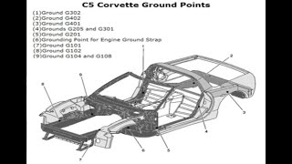
Est. part cost: $5-$50 - Poor or Corroded Ground Connections 🟡 Medium Probability Corvettes have numerous ground points, and a loose or corroded ground can introduce electrical noise and communication faults. Owners on forums report success tracing U0073 to bad grounds, especially those near the battery, on the frame rails in the engine bay, or near the starter. Some factory grounds were bolted over painted surfaces, leading to poor long-term contact. 🎬 See this guide on locating and cleaning C6 ground wires.
How to confirm: Locate the main ground points (G102, G300, etc.) for the BCM, ECM, and chassis using a service manual or forum diagrams. Disconnect, clean the contact surfaces to bare metal, and securely retighten them. Perform a voltage drop test on the ground circuit.
Typical fix: Cleaning and tightening ground connections. Some owners add supplementary ground straps from the engine to the frame.
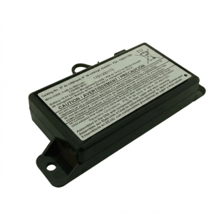
Est. part cost: $0-$20 - Weak or Failing Battery 🟡 Medium Probability → Shop Vehicle Battery Modern control modules are sensitive to voltage. If the battery voltage drops too low during startup, modules may not initialize correctly, causing a flood of communication faults including U0073. 🎬 Watch: A mechanic explains what the U0073 code really means. This is a common issue on many modern, electronically-dense vehicles.
How to confirm: Test the battery with a multimeter. It should read at least 12.4 volts with the engine off. Check the charging system to ensure it's between 13.8 and 14.5 volts while running. Load test the battery to confirm its health.
Typical fix: Recharge or replace the battery.
Est. part cost: $150-$350 - Damaged CAN Bus Wiring ⚪ Low Probability Wiring can become chafed, pinched, or damaged from vibrations, previous repairs, or rodent activity. A common chafe point is where the harness passes near the fuse box in the passenger footwell or near the EBCM. A short or open in the twisted pair of CAN wires (typically Tan and Tan/Black) will bring the network down.
How to confirm: Visually inspect harnesses in the engine bay, under the dash, and near the fuse box. With the battery disconnected, check for 60 ohms of resistance across pins 6 and 14 of the OBD-II port. A reading of 120 ohms indicates a break in the circuit 🎬 Watch: How to diagnose and fix common CAN bus communication issues. or a bad terminating resistor, while a reading near 0 ohms indicates the wires are shorted together.
Typical fix: Repair the damaged section of wiring, ensuring the repaired wires are twisted together to maintain network integrity.
Est. part cost: $5-$100
Rare But Worth Checking
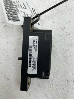
- Failing Control Module (EBCM/ABS): While often suspected first, a module failing and bringing down the whole network is less common than wiring issues. However, on the C6 Corvette, the Electronic Brake Control Module (EBCM/ABS module) is a known point of failure that can cause a U0073 code. One owner on CorvetteForum traced the issue to a faulty ABS module by pulling its fuse, which restored communication and allowed the transmission to shift properly. The module is located in a tight spot between the engine and radiator, and internal solder joints can fail.
- Corroded BCM or Fuse Box Connectors: The Body Control Module (BCM) is located in the passenger footwell and is a central hub for communication. Water leaks from the cowl or a clogged A/C drain can lead to corrosion on its connectors, causing network failure. Similarly, the underhood fuse box connections can become corroded, leading to intermittent communication problems.
- Aftermarket Electronics Interference: Poorly installed remote starters, alarms, or stereos can interfere with the CAN bus network if they are tapped into the wrong wires, causing data corruption.
Diagnosis Steps
- Check and fully charge the battery. Ensure terminals are clean and tight. Low voltage is a common cause of communication codes.
- Scan all modules for codes. Note which modules are not communicating and which codes are present. A professional scan tool is needed for this.
- Perform a thorough visual inspection of the main wiring harnesses, especially the 16-way connector at the transmission, for backed-out pins, corrosion, or fluid contamination as noted in TSB #08-07-30-021H.
- Inspect and clean all major power and ground connections for the ECM, BCM, and chassis. Key C6 ground locations are on the frame rails near the engine and behind the passenger seat area.
- With the battery disconnected, measure the resistance between Pin 6 (CAN High) and Pin 14 (CAN Low) at the OBD-II port. A healthy network should read approximately 60 ohms.
- If the resistance is 120 ohms, it indicates an open circuit or a faulty terminating resistor (one is in the ECM, the other can be in the BCM or a separate resistor). If it's near 0 ohms, the CAN wires are shorted together.
- If wiring and grounds are good, the issue may be a single module bringing down the network. A diagnostic technique is to disconnect modules one by one to see if communication is restored. A common culprit on the C6 is the EBCM (ABS module); try pulling the ABS fuse to see if the U0073 code disappears and other systems return online.
Parts You'll Likely Need
- Wiring Harness Connector Pigtail — If the transmission harness connector is damaged or contaminated beyond cleaning, a new pigtail may be required.
- Connector Terminals — Individual terminals within a connector (like the 16-way transmission plug) can be replaced if they are corroded or have lost tension.
- Electronic Brake Control Module (EBCM) — If the EBCM is identified as the module pulling the network down, it will need to be repaired or replaced.
- Battery — If the battery fails a load test or cannot hold a proper charge, it must be replaced to ensure stable voltage for all modules.
Related Codes That Often Appear With This One
- P0700 — This is a generic code from the ECM indicating that the Transmission Control Module (TCM) has stored a fault code. It frequently appears with U0073 because the TCM can no longer communicate with the ECM.
- U0100 — Lost Communication with ECM/PCM. This code is set by other modules when they can no longer hear from the engine computer, a direct result of the network being down (U0073).
- U0101 — Lost Communication with TCM. Set by other modules when they can't communicate with the transmission controller.
- U0121 — Lost Communication with Anti-Lock Brake System (ABS) Control Module. Set when the ABS module (EBCM) goes offline.
- U0140 — Lost Communication with Body Control Module (BCM). Set when the BCM, a central hub for many functions, goes offline.
Technical Service Bulletins (TSBs) & Recalls
- 08-07-30-021H
Platform-Specific Known Issues
- TSB #08-07-30-021H: This bulletin specifically addresses intermittent gauge fluctuation, door lock cycling, no-shift conditions, and a host of communication DTCs including U0073. It points to a backed-out terminal in the 16-way electrical connector to the automatic transmission as a primary cause.
Mechanic-Grade Diagnostic Values
- CAN Bus Network Resistance — expected: ~60 Ω (Ohms) across Pin 6 (CAN High) and Pin 14 (CAN Low) of the OBD-II port with the battery disconnected.. Failure: A reading of ~120 Ω indicates an open in the circuit or a failed terminating resistor. A reading near 0 Ω indicates the CAN High and Low wires are shorted together.
- CAN High Voltage (Key On, Engine Off) — expected: ~2.6V between Pin 6 of the OBD-II port and chassis ground.. Failure: Significant deviation from 2.5-3.0V can indicate a short or open on the CAN High line.
- CAN Low Voltage (Key On, Engine Off) — expected: ~2.4V between Pin 14 of the OBD-II port and chassis ground.. Failure: Significant deviation from 2.0-2.5V can indicate a short or open on the CAN Low line.
- Parasitic Drain (Sleep Mode) — expected: Should drop to 0.19A or lower after all modules go to sleep (several minutes after turning the car off).. Failure: A sustained draw of 3A or more, dropping to only around 0.19A after a minute, can indicate a module is not sleeping correctly and may be causing network issues.
Scan Tool Commands That Help
- Tech2 / GDS2: Module Status / Poll — To see which specific control modules are not communicating on the network. This is the first step in isolating the fault, as it tells you which modules are 'offline'.
- Tech2 / GDS2: Steering Wheel Position Sensor Recalibration — If a C1281 code is present alongside U-codes, or if the steering wheel has been removed. A faulty or uncalibrated SWPS can flood the network with bad data, causing communication faults. The tool can reset the sensor's zero point.
Wiring & Ground Locations
- G107 — Located on the left-hand (driver's side) rear of the engine block, near or on the bell housing.. This is a critical ground for the ignition coil packs. A loose G107 can cause a no-spark condition and may introduce electrical noise that disrupts module communication.
- G102 — Mounted to the left-hand (driver's side) frame rail, below the battery.. This is a major chassis ground point where other grounds, including G107, terminate. Corrosion or looseness here can cause widespread electrical issues.
- G106 — Passenger's side of the engine block, above the starter.. This serves as the main battery-to-engine ground and a ground for the PCM. A poor connection here can directly impact the ECM's ability to operate and communicate.
- EBCM Connector — The Electronic Brake Control Module is located between the engine and radiator. Its main connector is a 38-pin sealed unit.. The high-speed GMLAN wires (Tan and Tan/Black) pass through this connector at pins 26 and 27. Corrosion or backed-out pins here can take down the entire network.
- Terminating Resistors — Two 120-ohm resistors are on the high-speed GMLAN bus. One is internal to the Engine Control Module (ECM), and the other is internal to the Body Control Module (BCM).. These resistors are required to prevent signal reflections on the bus. If one of the modules containing a resistor fails or is disconnected, the total bus resistance will change from 60 ohms to 120 ohms, indicating a fault.
Real Owner Repair Stories
- CorvetteForum user (2006 Corvette C6 M6 Coupe) — Flurry of console messages for ABS, active handling, TC, fuel gauge at 0, service fuel system, and security light on.
❌ Tried (didn't work) Checking battery voltage (was 12.48V)., Initial parasitic draw test showed high amperage.
✅ What actually fixed it The user noted that after extensive diagnostics, the issue was traced to a faulty fuel level sensor, which communicates on the bus. The resolution pointed towards a module-level fault rather than a simple wiring break. - CorvetteForum user (C6 Z06 (year not specified)) — Car would not start, no communication with modules.
❌ Tried (didn't work) Jumping pairs of CAN wires (Tan and Tan/Black) together.
✅ What actually fixed it The problem was resolved by adding a 120-ohm resistor between the CAN wires after removing the EBCM, which contains one of the network's terminating resistors. This manually restored the required 60-ohm total bus resistance, allowing the remaining modules to communicate. This points to a failed EBCM.
Model Year Variations Within This Range
- 2005-2007: These models used the 6.0L LS2 engine and a 4-speed automatic transmission (in 2005) or the first-generation 6-speed automatic (2006-2007). The steering feel was also noted to be less refined.
- 2008-2013: The 2008 model year introduced significant updates, including the 6.2L LS3 engine, an improved TR6060 manual transmission, and revised steering for better feel. These changes also brought updates to the control modules and their software, which can affect diagnostics.
- 2005-2009: The Steering Wheel Position Sensor (SWPS) is a known failure point on these earlier C6 models.
Helpful Videos


Used OEM Parts in Stock
New Aftermarket Parts Available

The information in this article is provided for general reference and educational purposes only. Vehicle specifications, procedures, and part compatibility can vary by production date, trim level, and region. Always consult your vehicle's factory service manual and verify part numbers before purchasing or performing repairs. Safety-critical components such as airbags, seat belts, and braking systems should be installed by a qualified professional.
- Chevrolet CORVETTE:
- 🧭 Diagnostic Flowchart
- 🎬 Helpful Videos
- 🛍️ Shop This Part
- What's Unique About the 2007-2014 Chevrolet CORVETTE
- Symptoms You May Notice
- Most Likely Causes
- Rare But Worth Checking
- Diagnosis Steps
- Parts You'll Likely Need
- Related Codes That Often Appear With This One
- Technical Service Bulletins (TSBs) & Recalls
- Platform-Specific Known Issues
- Mechanic-Grade Diagnostic Values
- Scan Tool Commands That Help
- Wiring & Ground Locations
- Real Owner Repair Stories
- Model Year Variations Within This Range
- 🎟️ Get 5% Off