
U0140 on 2007-2014 Chevrolet Corvette: Lost BCM Communication Causes and Fixes
On a 2007-2014 Corvette, code U0140 typically indicates a network communication failure with the Body Control Module (BCM), often caused by corroded or loose connectors rather than a failed BCM. Inspecting the BCM connectors (especially the blue ones) in the passenger footwell and checking for water intrusion are the most common first steps.
- U0140 on a Corvette is most often a wiring or connector issue, not a bad BCM.
- Before any other diagnostics, check the large connectors on the Body Control Module in the passenger footwell for a secure fit.
- Inspect and clean the battery terminals and main ground connections, as low voltage can cause network errors.
- Refer to GM TSB #08-07-30-021H, which specifically addresses this code and points to known problem areas like the transmission harness connector.
- Do not replace the BCM unless all other potential causes have been thoroughly investigated, as a new module is expensive and requires programming.
What's Unique About the 2007-2014 Chevrolet CORVETTE
The 2007-2014 Corvette, which spans the C6 and the first year of the C7 generation, is specifically named in GM Technical Service Bulletin #08-07-30-021H for network communication issues. Unlike many vehicles where this code might point to a failed module, on the Corvette, it's frequently caused by intermittent poor connections at the BCM itself (located in the passenger footwell) or other major network connectors. Owners on CorvetteForum often report that simply reseating a loose BCM connector resolves a host of bizarre electrical issues, sometimes caused by a passenger's feet pushing on the connectors. Water leaks into the passenger footwell from clogged A/C drains or cowl vents are also a known issue that can lead to corrosion on the BCM and its connectors.
Diagnostic Flowchart
Tap your situation to follow the diagnostic path that matches what you're seeing on this vehicle.
Generation note: This range covers the end of the C6 generation (2007-2013) and the first year of the C7 generation (2014). While the underlying cause is often similar (network communication), the specific locations of connectors and grounds may differ. The BCM in the C6 is well-documented as being in the passenger footwell; C7 owners should verify location. TSB #08-07-30-021H applies to both generations.
Symptoms You May Notice
- Multiple warning lights on the instrument panel (Service Active Handling, Service ABS, etc.).
- Intermittent no-crank or no-start condition.
- Engine may stall while driving.
- Instrument panel gauges fluctuating, going dead, or fuel gauge reading zero.
- Transmission may not shift correctly or may default to a lower gear.
- Power door locks cycling on their own.
- Interior or exterior lights not working correctly, flickering, or staying on.
- OBD-II port may be unresponsive, preventing communication with a scan tool.
- Radio or infotainment system problems.
- Parasitic battery drain when the vehicle is off.
- Replacing the BCM without first checking all connectors, wiring, and grounds. The issue is very often a simple connection problem that does not require an expensive new module.
- Replacing other modules like the TCM or ECM when the root cause is a network-wide communication fault originating from a bad connection elsewhere.
Most Likely Causes
- Poor Connection at Body Control Module (BCM) 🔴 High Probability → Shop Body Control Module Vibration, thermal cycles, and even pressure from a passenger's feet can cause the large connectors at the BCM to become loose or develop poor pin contact. Water intrusion from clogged A/C drains or cowl vents is a known C6 issue that can corrode these connectors. This is a widely reported issue in Corvette forums for the C6 generation.
How to confirm: With the battery disconnected, access the BCM in the passenger footwell. Disconnect the large connectors (often two blue and one gray or black) and inspect the pins for corrosion, moisture, or damage. Many owners report fixing the issue simply by wiggling or reseating these connectors.
Typical fix: Disconnect the BCM connectors, clean the pins with electrical contact cleaner, apply a small amount of dielectric grease to the connector seals (not the pins themselves), and ensure they are securely re-seated and locked.
Est. part cost: $5-$15 - Wiring Harness or Network Connector Issues 🟡 Medium Probability GM TSB #08-07-30-021H specifically calls out issues with chafed wiring, backed-out terminals, and corrosion in major GMLAN network connectors, including the 16-way transmission connector and star connectors.
How to confirm: Visually inspect key wiring harnesses for chafing, especially where they pass near the engine, transmission, or through the firewall. Check major inline connectors for corrosion or backed-out pins. A common failure point is the wiring near the transmission.
Typical fix: Repair any chafed or broken wires. Clean corroded connectors and ensure they are fully seated. The TSB provides detailed procedures for inspecting and repairing the transmission harness connector.
Est. part cost: $10-$100 - Weak Battery or Poor Battery/Ground Connections 🟡 Medium Probability → Shop Vehicle Battery Control modules are sensitive to voltage. Low system voltage from a failing battery or high resistance from corroded battery terminals or ground straps can cause modules to drop off the communication network. A battery voltage below 12.4V at rest can start causing issues.
How to confirm: Test the battery voltage; it should be above 12.4V at rest. Perform a load test on the battery. Inspect all main power and ground connections for tightness and corrosion, including the battery terminals, main chassis grounds (especially those under the battery tray), and engine block grounds.
Typical fix: Clean battery terminals and ground points thoroughly with a wire brush. Replace the battery if it fails a load test.
Est. part cost: $20-$250 - Failed Body Control Module (BCM) ⚪ Low Probability → Shop Body Control Module While less common than connection issues, the BCM can fail internally due to solder joint fatigue or water intrusion. On early C6 models, some BCMs have been discontinued, making replacement with a used or remanufactured unit necessary.
How to confirm: This is typically diagnosed by exclusion. If all wiring, connectors, power, and grounds have been verified as good, the BCM itself is the likely culprit. A professional will use a scan tool to attempt direct communication with the BCM; if it's unreachable but the network wiring is good, the module has likely failed.
Typical fix: Replace the Body Control Module. The new module must be programmed to the vehicle's VIN using specialized tools like a Tech 2 or through a dealer service. Some services can clone an old BCM to a used one. 🎬 Watch: How to clone or reset a used BCM module.
Est. part cost: $300-$600
Rare But Worth Checking
- Aftermarket Device Interference:
Diagnosis Steps
- Check Battery Health: Ensure the battery has a full charge (12.4V+) and clean, tight terminals. A weak battery is a common cause of communication codes.
- Scan for All Codes: Use a high-quality scan tool (like a Tech 2) to read codes from all modules, not just the ECM. Note which other 'U' codes are present to understand the scope of the communication failure.
- Inspect BCM Connectors: Disconnect the negative battery terminal. Access the BCM in the passenger footwell. Carefully disconnect its connectors (often blue, gray, or black) and inspect for any signs of corrosion, moisture, or backed-out pins. Check for signs of water intrusion in the footwell area.
- Reseat Connectors: Even if they look good, firmly reseat all BCM connectors until they click and lock into place. Many owners have fixed the issue with this step alone. Reconnect the battery and see if symptoms resolve.
- Inspect Main Grounds: Check the main battery ground and other major chassis ground points (e.g., under the battery tray) for clean, tight connections.
- Check CAN Bus Resistance: With the battery disconnected, use a multimeter to measure the resistance between Pin 6 (CAN High) and Pin 14 (CAN Low) on the OBD-II port. A healthy network should read approximately 60 ohms. A reading of 120 ohms indicates a missing termination resistor or an open circuit, while a reading near 0 ohms indicates a short circuit.
- Inspect Network Wiring: Following the guidance in TSB #08-07-30-021H, inspect the GMLAN wiring harness, paying close attention to the 16-way transmission connector and any areas where the harness may chafe against the frame or engine components.
- Professional Diagnosis: If the problem persists, a professional technician will be needed to perform advanced network diagnostics, such as checking for shorts or opens in the data lines and using a scan tool to isolate the faulty module or wiring section.
Parts You'll Likely Need
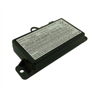
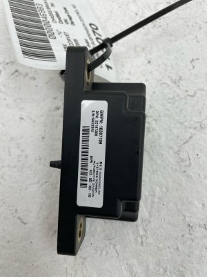
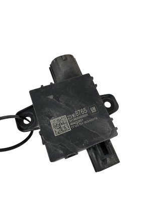
- Body Control Module (BCM)
(OEM #Varies by year. Examples: 15850986 (2006), 25790451 (2007), 20934684 (2008-2013))
Related Codes That Often Appear With This One
- U0073 — This code for 'Control Module Communication Bus A Off' is a general network failure code often set alongside U0140 and is explicitly mentioned in TSB #08-07-30-021H.
- U0100 — Lost Communication with ECM/PCM. This can be set in other modules when a wiring fault or the BCM dropping offline disrupts the entire network.
- U0101 — Lost Communication with TCM. The transmission connector is a known problem area mentioned in TSB #08-07-30-021H, making this code common.
- U0121 — Lost Communication with ABS Control Module. The ABS module is another critical component on the high-speed network that will log a code if communication is disrupted.
Technical Service Bulletins (TSBs) & Recalls
- TSB #08-07-30-021H: Loss of High Speed GMLAN Communications, Intermittent No Crank, IP Gage Fluctuation, and other symptoms. This is the primary document for diagnosing network issues on this platform.
Platform-Specific Known Issues
- Loose BCM connectors in the passenger footwell are a very common cause of widespread, intermittent electrical problems on the C6 Corvette. Forum members frequently advise checking these connections first, as they can be dislodged by a passenger's feet.
- Water intrusion into the passenger footwell from clogged A/C evaporator drains or cowl drains is a known C6 vulnerability that can lead to corrosion and failure of the BCM and its connectors.
- The 16-pin transmission harness connector is a specific point of failure mentioned in TSB #08-07-30-021H, which can cause this code along with transmission-specific symptoms.
Mechanic-Grade Diagnostic Values
- High-Speed GMLAN Bus Resistance — expected: Approximately 60 ohms (± 3 ohms). Failure: A reading of 120 ohms suggests an open circuit or a missing terminating resistor (one in ECM, one in BCM). A reading near 0 ohms indicates a short between the CAN high and low wires.
- High-Speed GMLAN Bus Voltage (Key On, Engine Off) — expected: CAN High (Pin 6 at DLC) should be ~2.5V to 3.5V. CAN Low (Pin 14 at DLC) should be ~2.5V to 1.5V. Both wires will show ~2.5V at rest.. Failure: Voltages that are stuck high, low, or do not mirror each other during communication indicate a bus fault. For example, a reading of 4.8V on CAN high is abnormal.
- GMLAN Wires to Ground Resistance (Battery Disconnected) — expected: Approximately 7,000-8,000 ohms (7-8 kOhms) from Pin 6 to ground (Pin 4/5) and Pin 14 to ground (Pin 4/5).. Failure: Significantly different readings between the two lines indicates an unbalanced bus. Very low resistance indicates a short to ground.
- BCM Relay Trigger Voltage — expected: Should be close to battery/system voltage (~12V).. Failure: A reading significantly lower, such as 10V, can indicate high resistance in the BCM's power or ground circuit, preventing proper relay actuation.
Scan Tool Commands That Help
- Tech II: BCM Setup — After replacing and SPS flashing a new or used BCM, a technician must use the Tech II to enter the BCM setup menu. This is used to verify or change settings like country of operation, transmission type (M6 or Auto), and to enable or disable features based on the vehicle's RPO code list (e.g., deselecting factory navigation if an aftermarket radio is installed).
Wiring & Ground Locations
- BCM — In the passenger footwell, integrated with the interior fuse block.. This is the module that has lost communication. Its connectors are prone to looseness from passenger foot traffic and corrosion from water leaks.
- G202 — On the passenger side, at the bottom of the A-pillar, behind trim panels.. This is a primary ground point for the BCM and I/P Relay Block. High resistance at this ground can cause low voltage to the BCM, triggering communication faults.
- G201 — On the driver's side, at the bottom of the A-pillar/threshold area, below the dash.. This ground serves the instrument panel cluster and HUD. A fault here can cause instrument panel symptoms that accompany a U0140 code.
- G302 — Behind the passenger B-pillar (halo) trim panel.. This is another key ground point on the passenger side that can affect various body electronics.
- SP205 / SP208 — SP205 is a Class 2 serial data splice pack located under the left side of the instrument panel, near the DLC. SP208 is under the right side of the instrument panel.. These splice packs are junction points for the communication network. While the main issue is often on the High-Speed GMLAN, faults in the Class 2 network can also cause widespread communication DTCs.
- GMLAN Terminating Resistors — Two 120-ohm resistors are used. One is internal to the Engine Control Module (ECM) and the other is internal to the Body Control Module (BCM).. These resistors are critical for network integrity. The BCM being one of the termination points makes its connection vital. A failure of either module or the wiring between them will cause the total bus resistance to change from 60 ohms to 120 ohms.
Real Owner Repair Stories
- CorvetteForum user mtchcnner (2007 Corvette) — BCM got wet, causing multiple electrical issues. After cleaning, the car would intermittently have no power and fail to start.
❌ Tried (didn't work) Initial cleaning fixed most problems, but a no-start condition persisted.
✅ What actually fixed it The owner resolved the intermittent no-power/no-start by disconnecting and reconnecting the negative battery terminal. This suggests the BCM was still faulty or had residual issues from the water damage, as a full reset was required to restore function temporarily. The ultimate fix would likely be BCM replacement.
OEM Part Supersession History
15288103→N/A (Specific to 2005)— Model year specific design.
Heads up: The 2005 BCM is unique and not directly interchangeable with later years.15850986→25790451 (for 2007)— Internal revisions and updates.
Heads up: The 2006-2007 BCMs are different from the 2008+ units and cannot be used in their place.25879086 / 20759656 / 15862140→20934684— Consolidation of part numbers for later model years.
Heads up: The 2008-2013 BCMs are generally interchangeable within that range but are not backward compatible with 2005-2007 models. A used BCM must have its VIN chip physically swapped or be cloned, as the VIN cannot be reprogrammed.
Model Year Variations Within This Range
- 2005-2007 vs 2008-2013: The BCM part numbers and internal architecture are different between these two groups. A BCM from a 2008+ car is not compatible with a 2007 or earlier model, and vice-versa.
- 2009+: Some wiring harnesses were redesigned, and a ground point (G402 on the passenger's side rear axle) was eliminated on some later models, though the frame stud may still be present.
Helpful Videos
We Have This Part in Stock

The information in this article is provided for general reference and educational purposes only. Vehicle specifications, procedures, and part compatibility can vary by production date, trim level, and region. Always consult your vehicle's factory service manual and verify part numbers before purchasing or performing repairs. Safety-critical components such as airbags, seat belts, and braking systems should be installed by a qualified professional.
- Chevrolet CORVETTE:
- 🧭 Diagnostic Flowchart
- 🎬 Helpful Videos
- 🛍️ Shop This Part
- What's Unique About the 2007-2014 Chevrolet CORVETTE
- Symptoms You May Notice
- Most Likely Causes
- Rare But Worth Checking
- Diagnosis Steps
- Parts You'll Likely Need
- Related Codes That Often Appear With This One
- Technical Service Bulletins (TSBs) & Recalls
- Platform-Specific Known Issues
- Mechanic-Grade Diagnostic Values
- Scan Tool Commands That Help
- Wiring & Ground Locations
- Real Owner Repair Stories
- OEM Part Supersession History
- Model Year Variations Within This Range
- 🎟️ Get 5% Off